
In the previous article, I showed how to do the initial build of our Mantis robot, featuring a RoboClaw motor controller board and a Raspberry Pi. Here, I’ll move on to attaching motors, connecting the RoboClaw to your Pi through a USB port, and supplying the RoboClaw with its own power source.
The RoboClaw Controller
The Roboclaw series of motor controller starts with a model that can control two motors at up to 7 amps each and ranges up to controlling two motors at 160 amps each with many models in between. I’ll be using the 45-amp model, which is available in two versions: one with pin heads for rotary encoders and the other with screw terminals for those connections.
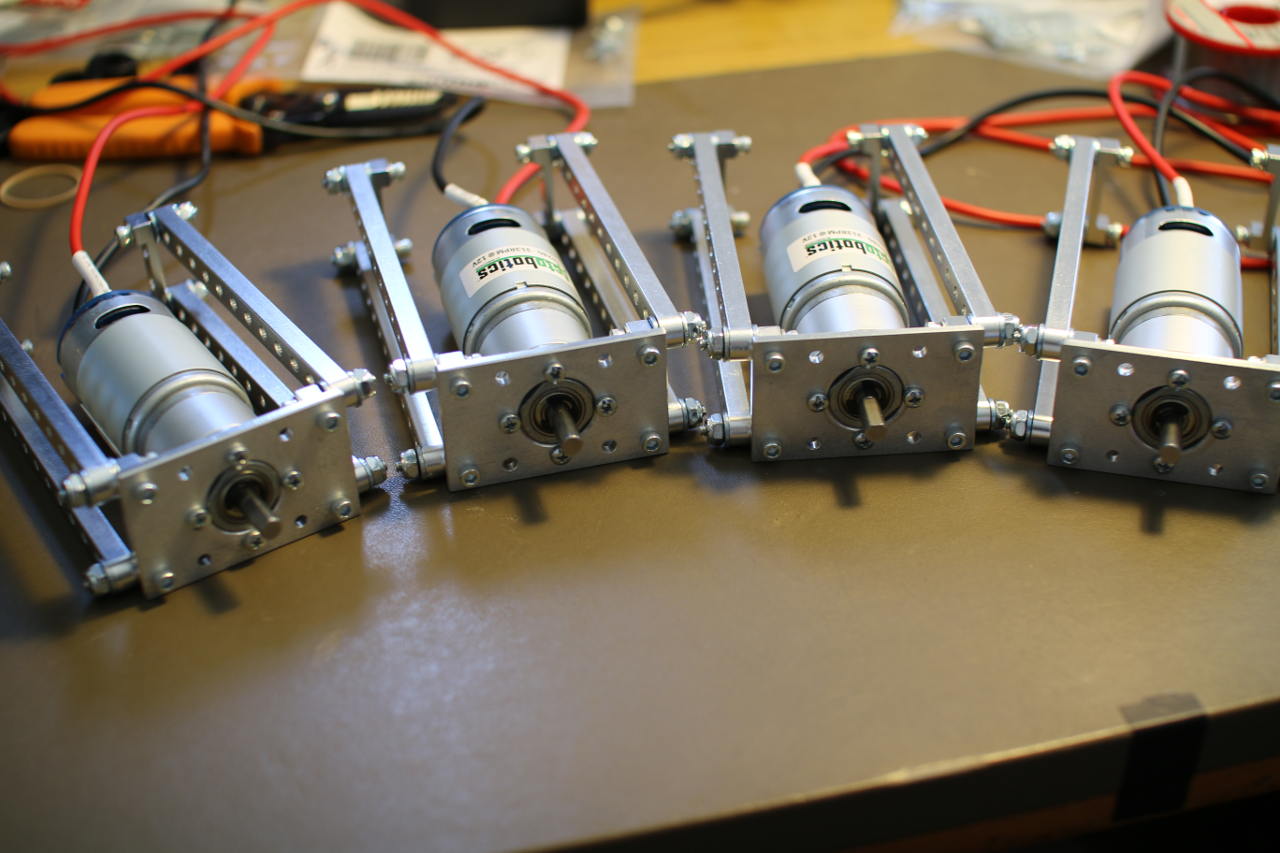
Attaching Motors
You might be wondering how the motors on the Mantis will be driven using a motor controller that has two outputs. All of the motors on the left side of the Mantis use one motor output and all of the motors on the right side use the other output. To turn left, all the motors on the left side will be set to turn at the same slower rate than all the motors on the right side of the Mantis. Because each of the x motors on one side of the Mantis is connected to the same motor controller output in parallel, in a worst case if all the motors on the left side stall, they will each draw 20 amps, and the potential draw from the motor controller is 20x amps. For the four-wheel Mantis, I used the 45-amp RoboClaw controller so the controller was happy to serve up enough power to run all the motors in a stalled state.
In the course of this build, I clarified some things with ON Motion Control (ionmc) who make the RoboClaw board. According to ionmc, each Roboclaw will handle over-current cases automatically. The maximum current that can be supplied is limited by the temperature of the RoboClaw board. “For example under 85 C the 2x45amp and 2x30amp [RoboClaw] can output up to 60 amps (the amount will vary on a linear slope from 25 V to 85C. Once 85C is reached the current limit is at the rated current(eg 45a or 30a per channel). Once temperature goes over 85 C there is an over temperature current limit which will reduce the maximum current down to 0 amps when it reaches 100 C,” ionmc said.
Never leave an electric motor in a stalled state. It will generate a lot of heat and likely damage the motor. With the Mantis, one of the motors could stall for a bit as the tire it is driving encounters an obstacle on the ground. That’s ok, as long as the Mantis gets over that obstacle; then the motor will revert to drawing significantly less current and not become damaged. Looking at the above quote, the 30 amp RoboClaw controller might be able to drive a six-wheel Mantis — even though the three wheels on a single output might draw 60 amps if they all stall. As long as the RoboClaw doesn’t heat up to 100C, it should still provide power. If a stall is prolonged, then the RoboClaw might just heat up to 100C and stop supplying power to the motors automatically.
Other Connections to the RoboClaw
A USB port on the RoboClaw allows easy connection to the Raspberry Pi, but the USB port on the RoboClaw cannot power the RoboClaw. So, you will have to supply the RoboClaw with its own power source to talk to it over USB. There are two ways to do this: either having an explicit logic power supply on the “LB IN” pins or by installing the jumper on the LB-MB (logic battery from main battery) jumper header. My RoboClaw came with the jumper on the LB-MB header already.
The RoboClaw has many input modes that let you tell the RoboClaw what to do using wireless receivers, serial commands over TTL serial, or the USB port on the RoboClaw. The default mode of the RoboClaw is 7, which allows you to control it over USB. Mode 7, is packet serial control at address 0x80.
You must make sure the connect any battery to the RoboClaw with the correct orientation. Reversing the ground and power leads will result in hardware damage or worse. Connecting a 9V battery over the battery input terminals and connecting the microUSB to the Raspberry Pi resulted in the following when looking at the output of dmesg.
root@pi:~# dmesg | tail
...
[ 3585.758555] cdc_acm 1-1.4:1.0: ttyACM0: USB ACM device
[ 3585.760209] usbcore: registered new interface driver cdc_acm
[ 3585.760229] cdc_acm: USB Abstract Control Model driver for USB modems and ISDN adapters
root@pi:~# ls -l /dev/*ACM*
crw-rw---T 1 root dialout 166, 0 Dec 22 07:16 /dev/ttyACM0
root@pi:~# lsusb -v > /tmp/lsusb.txt
root@pi:~# emacs /tmp/lsusb.txt
...
 idVendor           0x03eb Atmel Corp.
 idProduct          0x2404
 bcdDevice            1.00
 iManufacturer           1
 iProduct                2 USB Roboclaw 2x45A
This output tells you that the RoboClaw should be at /dev/ttyACM0. Instead of using that magic value, it can be convenient to have udev create a link for you to the correct device file.
The below 99-roboclaw.rules file will have a /dev/roboclaw device created whenever you connect the RoboClaw to a USB port on the Raspberry Pi. A huge advantage here is that, if you connect something else to a USB port that creates a /dev/ttyACM device, you don’t have to wonder if the RoboClaw is now at /dev/ttyACM0 or /dev/ttyACM1; it should still be available at /dev/roboclaw.
root@pi:~# cat /etc/udev/rules.d/99-roboclaw.rules
ACTION=="add", ATTRS{idProduct}=="2404", ATTRS{idVendor}=="03eb", SYMLINK+="roboclaw"

root@pi:~# l /dev/roboclaw
lrwxrwxrwx 1 root root 15 Dec 22 07:24 /dev/roboclaw -> bus/usb/001/005
Talking to the RoboClaw from the Raspberry Pi
To ensure that the connection to the RoboClaw is working, as good test is to ask the RoboClaw what version board it is and what firmware it is running. The command number 21 does this. Because you can have multiple RoboClaw controllers on a single bus, each command starts with the address of the RoboClaw you are wanting to talk to. The default RoboClaw address is 0x80 — which is what I’m using in the example. The RoboClaw address is mainly useful if you want to have multiple RoboClaw controllers connected to the same TTL serial interface. If you are connecting to the RoboClaw over USB, then each RoboClaw can have the default address of 0x80, because each will have a different serial device on the Linux machine.
Boost is a common collection of libraries used in C++ programming. It includes support for many things, such as intrusive reference counting, collections, graph library, parser generator, and more. The following C++ source code uses boost and boost::asio to talk to the RoboClaw over the USB cable and get the version from the RoboClaw. The boost::asio lets you talk to networks and low-level I/O, which is used below to perform serial communication over the USB port.
#include <boost/asio.hpp>
#include <boost/asio/serial_port.hpp>
#include <boost/bind.hpp>
#include <boost/integer.hpp>
using namespace boost;
using namespace boost::asio;
#include <string>
#include <iostream>
using namespace std;
int main( int argc, char** argv )
{
std::string serialDev = "/dev/roboclaw";
const uint8_t roboclawAddress = 0x80;
if( argc > 1 )
{
serialDev = argv[1];
}
cerr << "serialDevice:" << serialDev << endl;
boost::asio::io_service io;
boost::asio::serial_port serial( io, serialDev );
// issue the "Read Firmware Version" command 21
// to the RoboClaw at 0x80
uint8_t commands[] = { roboclawAddress, 21 };
write( serial, boost::asio::buffer(commands, 2));
// give the RoboClaw heaps of time to reply.
sleep(1);
// read the result
string ver = "";
char c = 0;
bool reading = true;
while( reading )
{
asio::read(serial,asio::buffer(&c,1));
switch(c)
{
case '�':
// also read the crc
asio::read(serial,asio::buffer(&c,1));
asio::read(serial,asio::buffer(&c,1));
reading = false;
break;
default:
ver+=c;
}
}
cout << "version: " << ver << endl;
return 0;
}
The getversion command should give you something like the following result.
pi@pi ~/src/roboclaw $ ./getversion
serialDevice:/dev/roboclaw
version: USB Roboclaw 2x45a v4.1.13
Next Time
In the rest of this series, I’ll extend the communication with the RoboClaw motor controller, leading to a program to control the robot with the keyboard. I will then move on to using a PS3 joystick to control the robot over Bluetooth. This should give you are powerful robot base that can happily adventure outdoors.
This is a great base platform with which to start playing with perception and semi-autonomous robot control. Delving deeper, you might like to add some feedback mechanism to the wheels of your Mantis so that you know how far you have traveled. You might also like to run a robotics platform such as ROS on top of an Ubuntu Linux installation on your Mantis.
I would like to respectively thank ServoCity and ION Motion Control for supplying the Mantis 4WD Robot Kit and RoboClaw Motor Controller used in these articles. ServoCity also provided a Raspberry Pi Channel mount and RoboClaw mount to help complete the build quickly.


