
In parts 1 and 2 of this series, we took at look at building and powering the Mantis robot kit (pictured above). A Raspberry Pi was mounted to it, and I described how to get the Pi talking to a RoboClaw motor controller. This time, I will show how to move the robot around using with the keyboard or a PS3 controller.
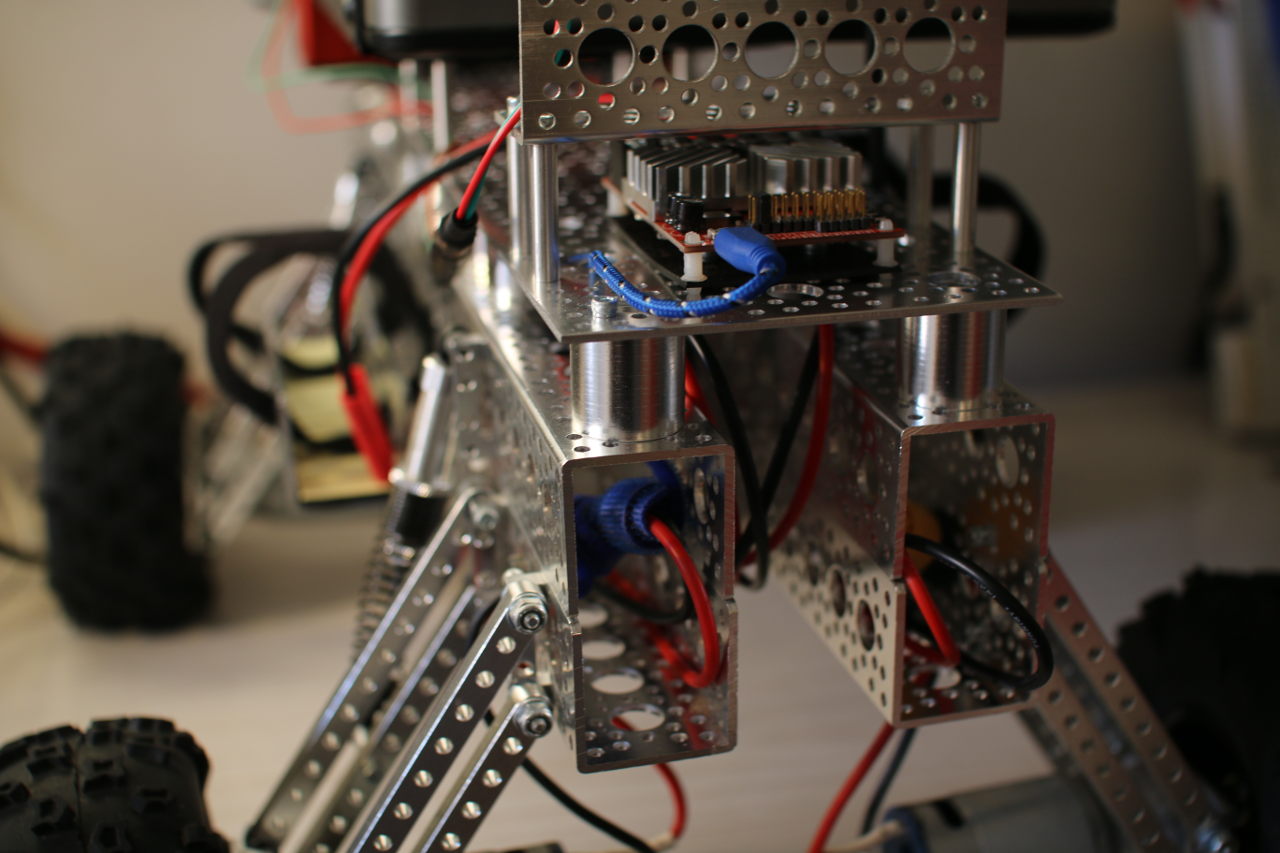
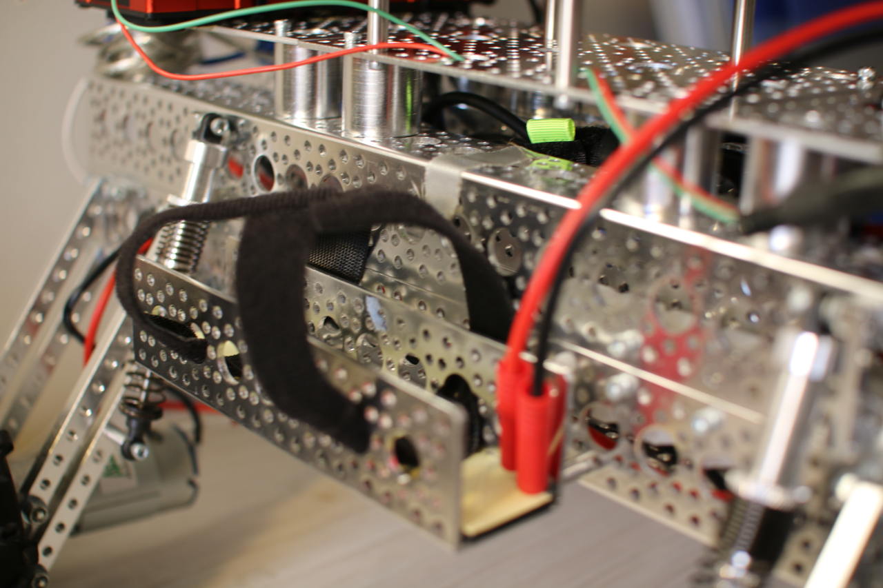
Before that, however, I want to mention a couple of modifications that you might want to consider. One very useful addition to a Mantis kit is to get two more 18-inch channels with the screw plates and use two 3-inch channels to separate the 18-inch sides from each other. On top of that, some 1-inch standoffs can separate three 4.5×6-inch flat channels to give a nice surface that you can connect things to (Figure 1).
The RoboClaw Class
It is convenient to encapsulate the communication with the RoboClaw controller into a RoboClaw class that provides nice methods and uses types that are expected on a computer rather than a microcontroller. For example, you might like to know the current voltage of the main battery as a floating point value to treat as a voltage rather than as an integer, which is a value in 0.1 volts or 0.01 volts.
The following code is a rewrite of the getversion command using the new RoboClaw class. The getVersion method will be issuing the same command 21 to the RoboClaw, but it is much simpler and more natural for the C++ program to simply call getVersion().
#include <boost/asio.hpp>
#include <boost/asio/serial_port.hpp>
#include <boost/bind.hpp>
#include <boost/integer.hpp>
using namespace boost;
using namespace boost::asio;

#include <string>
#include <iostream>
using namespace std;

#include "RoboClaw.h"

int main( int argc, char** argv )
{
   std::string serialDev = "/dev/roboclaw";

   if( argc > 1 )
   {
       serialDev = argv[1];
   }
   cerr << "serialDevice: " << serialDev << endl;

   boost::asio::io_service io;
   RoboClaw rc( io, serialDev );

   for( int i=0; i<10; i++ )
   {
       cout << "version        : " << rc.getVersion() << endl;
       cout << "battery voltage: " << rc.getBatteryVoltageMain() << endl;
       cout << "temperature    : " << rc.getTemperature() << endl;
       sleep(1);
   }
   return 0;
}
The RoboClaw::getBatteryVoltageMain() is code we haven’t seen before. It uses the private issueCommandU16() method to send a command that expects a 16-bit number as the result. The getVersion() method just issues the command and returns the result read from the RoboClaw. Communication with the RoboClaw is protected with a two-byte CRC.
For getVersion(), I just read those bytes and didn’t bother to check that they were valid. For issueCommandU16(), the CRC is calculated locally and compared with the CRC read from the RoboClaw after issuing the command. If these CRCs do not match, then something very bad has happened, and we should know about that rather than continuing to drive the robot assuming that everything is fine.
To track the CRC, the issueCommandU16() method uses writeTrackCRC() instead of directly calling write(). The writeTrackCRC() will first zero the CRC member variable and then calculate it for every byte it writes. The read2() method by default updates the CRC member variable to include each byte that was read. The crcOK can then read the two-byte CRC from the RoboClaw (without updating the CRC member variable) and throw an exception if the read CRC does not match the expected value.
float
RoboClaw::getBatteryVoltageMain()
{
   float ret = issueCommandU16( 24 );
   return ret / 10.0;
}

uint16_t
RoboClaw::issueCommandU16( uint8_t cmd )
{
   uint8_t commands[] = { roboclawAddress, cmd };
   writeTrackCRC( boost::asio::buffer(commands, 2));
   uint16_t ret = read2();
   crcOK();
   return ret;
}
Keyboard Robot Drive
A duty cycle simply describes what percentage of time you want to run an electric motor. A duty cycle of 50 percent will run the motor about half the time. Note that the power to the motor might turn on and off many times extremely quickly, so you won’t notice that this is happening.
The above RoboClaw class and driver program can be extended to allow the motors to be controlled from the keyboard. The main() driver program below uses the new MantisMovement and InputTimeoutHandler classes.
The console program uses curses to present the robot state to the user and to read keys from the keyboard without blocking. You also get handing of the keyboard arrows using the keypad() curses function. The screen is set up using the code shown below. A window ‘w’ is created so that specific settings can be applied to the window.
initscr();
noecho();
w = newwin( 0, 0, 0, 0 );
keypad( w, true );
timeout(1);
wtimeout(w,1);
This setup is the same as getversion2 above, but we create instances of MantisMovement and InputTimeoutHandler for later use.
boost::asio::io_service io;
RoboClaw rc( io, serialDev );
MantisMovement mm;
InputTimeoutHandler timeoutHandler;
The main loop begins by checking how long it has been since a keyboard input was received from the user. After 1 second, we clear the display of the last movement command from the screen. After 5 seconds, it is assumed that there is a problem with input and the robot is stopped before the program exits.
Notice that the rampDown() call takes the current power level that is used for the left and right wheels. The rampDown() method will gradually, but over a fairly short time interval, slow down each motor to a stop. This is to make a nicer stop if the robot happened to be running at full speed when communications were lost, it’s better to try to stop gradually than to tell the motors to stop instantly.
while( true )
{
   uint32_t diff = timeoutHandler.diff();
   if( diff > 1 )
   {
       mvwprintw( w,1,1,"      " );
   }
   if( diff > 5 )
   {
       mvwprintw( w,1,1,"TIMEOUT  " );
       wrefresh(w);

       std::pair< float, float > d = mm.getActiveDuty();
       rc.rampDown( d.first, d.second );

       sleep(5);
       break;
   }
The rest of the main loop reads a character from the input — if there is one — and adjusts the speed and heading of the robot to reflect the user input. Finally, the current settings are shown to the user and the speed of each motor is set using RoboClaw::setMotorDuty().
   int c = wgetch( w );
   if( c > 0 )
   {
       timeoutHandler.update();

       const float incrSpeed = 0.5;
       const float incrHeading = 0.05;
       if( c == '0' )
           break;
       switch( c )
       {
           case KEY_LEFT:
               mvwprintw( w,1,1,"LEFT  " );
               mm.adjustHeading( -1 * incrHeading );
               break;
           case KEY_RIGHT:
               mvwprintw( w,1,1,"RIGHT " );
               mm.adjustHeading(  1 * incrHeading );
               break;
           case KEY_UP:
               mvwprintw( w,1,1,"UP    " );
               mm.adjustSpeed(  1 * incrSpeed );
               break;
           case KEY_DOWN:
               mvwprintw( w,1,1,"DOWN  " );
               mm.adjustSpeed( -1 * incrSpeed );
               break;
           default:
               mvwprintw( w,5,0,". have char: %d", c );
               break;
       }
   }

   std::pair< float, float > d = mm.getActiveDuty();
   mvwprintw( w,0,0,"speed: %+3.2f  heading: %+1.1f  d1:%+3f d2:%+3f",
              mm.getSpeed(),
              mm.getHeading(),
              d.first, d.second );

   rc.setMotorDuty( d.first, d.second );

   usleep( 20 * 1000 );
}
The new helper class MantisMovement is responsible for maintaining the robot’s speed and heading and allowing the values to be updated. When you set the speed or heading, the MantisMovement updates internal variables to allow you to get the duty cycle for the left and right motors. The MantisMovement class knows nothing about the RoboClaw class; it is only interested in working out what the duty cycle (from -100% to +100%) should be in order to give the desired speed and heading. If MantisMovement returns a negative duty cycle, then you need to turn the motors in a reverse direction.
In MantisMovement, the speed ranges between -100 and +100, and the heading ranges between -1 and +1. The adjustHeading updates a member variable and calls updateMotorDuty() to update what the duty cycle needs to be to give the desired movement. The updateMotorDuty() delegates to updateMotorDutyOnlyForwards(), which is shown below in simplified form.
The duty cycle for the left and right motors starts out has the desired speed and is then modified to take the desired heading into account. As the heading ranges from -1 to +1, if we simply add 1 to the heading, then we get a range from 0 to 2. If we multiply the left duty cycle by a number from 0 to 2, then we either stop the motor completely or double the speed depending on whether we want to turn fully left or fully right. To find the correct duty cycle, we can reverse the value range to 2-(0 to 2) to get a range of 2 down to 0.
Because there are multiple left and right wheels, each of which have quite a bit of grip on them, I found that letting any wheel stop during a turn was extremely bad. Robots with only two drive wheels might get away with holding a wheel stationary and pivoting on the spot, but this sort of turning doesn’t work well for the Mantis. So, the dampen factor was added to allow the range to be cut back. For example, a dampen value of 0.6 will allow the heading to generate a finally motor speed between 40 percent and 160 percent of the original speed.
void
MantisMovement::adjustHeading( float v )
{
   heading += v;
   if( heading > 1 )  heading = 1;
   if( heading < -1 ) heading = -1;
   updateMotorDuty();
}

void
MantisMovement::updateMotorDutyOnlyForwards( float dampen )
{
   d1 = speed;
   d2 = speed;

   // heading ranges from -1 to 1.
   float headingRangeOffset = 1;
   float headingRangeDelta  = 2;
   float h = heading * dampen;
   d1 = ( h + headingRangeOffset ) * d1;
   d2 = ( headingRangeDelta - (h + headingRangeOffset)) * d2;
}
The whole reason for the InputTimeoutHandler class to exist is to track whether user input has not been received for a given amount of time. The InputTimeoutHandler::update() method updates the internal timestamp to the current time. The diff() method returns the number of seconds since update() had been called. When a new keyboard event is received from the user, the update() is called. And, every time around the main loop, the diff() is used to check if no input has come in for too long. The diff() method uses timeval_subtract(), which is is adapted from the same function in the GNU libc manual.
Next Time
With the above tools, the robot can be controlled over WiFi using a keyboard to set the speed and control the direction. This is great to see that things are working as expected. In the next article, I’ll show you how to control the robot using a PS3 joystick to control the robot over Bluetooth. This is much easier than trying to juggle a keyboard while you are watching where you are going.
Read the previous articles in this series:
Build an Off-Road Raspberry Pi Robot: Part 1
Build an Off-Road Raspberry Pi Robot: Part 2


