For this three part series, we implemented a ‘pedal to the metal’ GPIO driven, flashing of a LED, in the context of a Linux kernel module for the NVIDIA Jetson Nano development board (kernel-based v4.9.294, arm64) in my favorite programming language … Ada!
- Part 1. Review of a kernel module, build strategy, and Ada integration.
- Part 2. Modeling of the problem in Ada.
- Part 3. Practical Ada binding to the C kernel APIs.
You can find the whole project published at https://github.com/ohenley/adacore_jetson. It is known to build and run properly. All instructions to be up and running in 5 minutes are included in the accompanying front-facing README.md. Do not hesitate to fill a Github issue if you find any problem.
Disclaimer: This text is meant to appeal to both Ada and non-Ada coders. Therefore I try to strike a balance between code story simplicity, didactic tractability, and features density. As I said to a colleague, this is the text I would have liked to cross before starting this experiment.
Pascal on steroids you quoted?
led.ads (specification file, Ada equivalent to C .h header file) is where we model a simple interface for our LED.
with Controllers;
package Led is -- this bit of Ada code provides an interface to our LED

  package C Renames Controllers;

  type State is (Off, On);
  type Led_Type (Size : Natural) is tagged private;

  subtype Tag Is String;

  procedure Init       (L : out Led_Type; P : C.Pin; T : Tag; S : State);
  procedure Flip_State (L : in out Led_Type);
  procedure Final      (L : Led_Type);

private

  for State use (Off => 0, On => 1);

  function "not" (S : State) return State is
      (if S = On then Off else On);
  type Led_Type (Size : Natural) is tagged record
      P     : C.Pin;
      T     : Tag (1 .. Size);
      S     : State;
  end record;

end Led;
For those new to Ada, many interesting things happen for a language operating at the metal.
- First, type are user-defined and strong. Therefore the compile-time analysis is super-rich and checking extremely strict. Many bugs do not survive compilation. If you want to push the envelope, move to the SPARK Ada subset. You can then start to prove your code for the absence of runtime errors. It’s that serious business.
- We with the Controllers package. Ada with is a stateless semantic inclusion at the language level, not just a preprocessor text inclusion like #include. Eg. No more redefinition contexts, accompanying guard boilerplate, and whatnot.
- Led is packaged. Nothing inside Led can clash outside. It can then be with’ed, and use’d at any scope. Ada scoping, namespacing, signature, etc. are powerful and sound all across the board. Explaining everything does not fit here.
- Here renames is used as an idiom to preserve absolute namespacing but code story succinct. In huge codebases, tractability remains clear, which is very welcomed.
- Ada enum State has full-image and range representation. We use a numeric representation clause, which will serve later.
- A tagged record lets you inherit a type (like in OOP) and use the “dot” notation.
- We subtype a Tag as a String for semantic clarity.
- out means, we need to have an initialized object before returning “out”, in out the passed “in” initialized object will be modified before returning “out”.
- Record (loosely a C struct equivalent) by specifying our Tag Size.
- We override the “not” operator for the State type as a function expression.
- We have public/private information visibility that lets us structure our code and communicate it to others. A neat example, because a package is at the language level, you remove any type in the public part, add data in the body file and you end up with a Singleton. That easy.
The driver translation
The top-level code story resides in flash_led.adb. Immediately when the module is loaded by the kernel, Ada_Init_Module executes, called from our main.c entry point. It first imports the elaboration procedure flash_ledinit generated by GNATbind, runs it, Init our LED object, and then setup/registers the delayed work queue.
with Kernel;
with Controllers;
with Interfaces.C; use Interfaces.C;
...
   package K renames Kernel;
   package C renames Controllers;

   Wq             : K.Workqueue_Struct_Access := K.Null_Wq;
   Delayed_Work   : aliased K.Delayed_Work; -- subject to alias by some pointer on it

   Pin            : C.Pin := C.Jetson_Nano_Header_Pins (18);
   Led_Tag        : Led.Tag := "my_led";
   My_Led         : Led_Type (Led_Tag'Size);
   Half_Period_Ms : Unsigned := 500;
...
procedure Ada_Init_Module is
   procedure Ada_Linux_Init with
      Import        => True,
      Convention    => Ada,
      External_Name => "flash_ledinit";
begin
   Ada_Linux_Init;
   My_Led.Init (P => Pin, T => Led_Tag, S => Off);
   ...

   if Wq = K.Null_Wq then -- Ada equal
      Wq := K.Create_Singlethread_Wq ("flash_led_wq");
   end if;

   if Wq /= K.Null_Wq then -- Ada not equal
      K.Queue_Delayed_Work(Wq,
                           Delayed_Work'Access, -- an Ada pointer
                           K.Msecs_To_Jiffies (Half_Period_Ms));
   end if;
end;
In the callback, instead of printing to the kernel message buffer, we call the Flip_State implementation of our LED object and re-register to the delayed work queue. It now flashes.
procedure Work_Callback (Work : K.Work_Struct_Access) is
begin
   My_Led.Flip_State;
   K.Queue_Delayed_Work (Wq,
                         Delayed_Work'Access, -- An Ada pointer
                         K.Msecs_To_Jiffies (Half_Period_Ms));
end;
Housekeeping
If you search the web for images of “NVIDIA Jetson Development board GPIO header pinout” you will find such diagram.
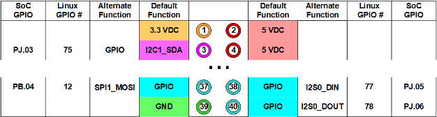
Right away, you figure there are about 5 data fields describing a single pinout
- Board physical pin number (#).
- Default function (name).
- Alternate function (name).
- Linux GPIO (#).
- Tegra SoC GPIO (name.#).
Looking at this diagram we find hints of the different mapping happening at the Tegra SoC, Linux, and physical pinout level. Each “interface” has its own addressing scheme. The Tegra SoC has logical naming and offers default and alternate functions for a given GPIO line. Linux maintains its own GPIO numbering of the lines so does the physical layout of the board.
From where I stand I want to connect a LED circuit to a board pin and control it without fuss, by using any addressing scheme available. For this we created an array of variant records instantiation, modeling the pin characteristics for the whole header pinouts. Nothing cryptic or ambiguous, just precise and clear structured data.
type Jetson_Nano_Header_Pin is range 1 .. 40; -- Nano Physical Expansion Pinout
type Jetson_Nano_Pin_Data_Array is array (Jetson_Nano_Header_Pin) of Pin_Data;

Jetson_Nano_Header_Pins : constant Jetson_Nano_Pin_Data_Array :=
      (1   => (Default => VDC3_3, Alternate => NIL),
       2   => (Default => VDC5_0, Alternate => NIL),
       3   => (Default       => I2C1_SDA,
               Alternate     => GPIO,
               Linux_Nbr     => 75,
               Port          => PJ,
               Reg_Bit       => 3,
               Pinmux_Offset => 16#C8#),
       4   => (Default => VDC5_0, Alternate => NIL),
...
      40   => (Default       => GPIO,
               Alternate     => I2S_DOUT,
               Linux_Nbr     => 78,
               Port          => PJ,
               Reg_Bit       => 6,
               Pinmux_Offset => 16#14C#));
Because everything in this Jetson_Nano_Header_Pins data assembly is unique and unrelated it cannot be generalized further, it has to live somewhere, plainly. Let’s check how we model a single pin as Pin_Data.
type Function_Type is (GPIO, VDC3_3, VDC5_0, GND, NIL, ..., I2S_DOUT);
type Gpio_Linux_Nbr is range 0 .. 255;        -- # cat /sys/kernel/debug/gpio
type Gpio_Tegra_Port is (PA, PB, ..., PEE, NIL);
type Gpio_Tegra_Register_Bit is range 0 .. 7;

type Pin_Data (Default : Function_Type := NIL) is record
   Alternate: Function_Type := NIL;
   case Default is
       when VDC3_3 .. GND =>
           Null; -- nothing to add
       when others =>
           Linux_Nbr     : Gpio_Linux_Nbr;
           Port          : Gpio_Tegra_Port;
           Reg_Bit       : Gpio_Tegra_Register_Bit;
           Pinmux_Offset : Storage_Offset;
   end case;
end record;
Pin_Data type is a variant record, meaning, based on a Function_Type, it will contain “variable” data. Notice how we range over the Function_Type values to describe the switch cases. This gives us the capability to model all pins configuration.
When you consult the Technical Reference Manual (TRM) of the Nano board, you find that GPIO register controls are layed out following an arithmetic pattern. Using some hardware entry point constants and the specifics of a pin data held into Jetson_Nano_Header_Pins, one can resolve any register needed.
Gpio_Banks : constant Banks_Array :=
   (To_Address (16#6000_D000#),
    ...
    To_Address (16#6000_D700#));

type Register is (GPIO_CNF, GPIO_OE, GPIO_OUT, ..., GPIO_INT_CLR);
type Registers_Offsets_Array is array (Register) of Storage_Offset;
Registers_Offsets : constant Registers_Offsets_Array :=
   (GPIO_CNF     => 16#00#,
    ... ,
    GPIO_INT_CLR => 16#70#);

function Get_Bank_Phys_Addr (Port : Gpio_Tegra_Port) return System.Address is
   (Gpio_Banks (Gpio_Tegra_Port'Pos (Port) / 4 + 1));

function Get_Register_Phys_Addr (Port : Gpio_Tegra_Port; Reg  : Register) return System.Address is
   (Get_Bank_Phys_Address (Port) +
    Registers_Offsets (Reg) +
   (Gpio_Tegra_Port'Pos (Port) mod 4) * 4);
In this experiment, it is mainly used to request the kernel memory mapping of such GPIO register.
-- led.adb (raw io version)
Base_Addr := Ioremap (C.Get_Register_Phys_Address (Pin.Port, C.GPIO_CNF), Control_C'Size);
Form follows function
Now, let’s model a common Pinmux register found in the TRM.
package K renames Kernel;
...
type Bit is mod 2**1;      -- will hold in 1 bit
type Two_Bits is mod 2**2; -- will hold in 2 bits

type Pinmux_Control is record
   Pm         : Two_Bits;
   Pupd       : Two_Bits;
   Tristate   : Bit;
   Park       : Bit;
   E_Input    : Bit;
   Lock       : Bit;
   E_Hsm      : Bit;
   E_Schmt    : Bit;
   Drive_Type : Two_Bits;
end record with Size => K.U32'Size;

for Pinmux_Control use record
   Pm         at 0 range  0 ..  1;  -- At byte 0 range bit 0 to bit 1
   Pupd       at 0 range  2 ..  3;
   Tristate   at 0 range  4 ..  4;
   Park       at 0 range  5 ..  5;
   E_Input    at 0 range  6 ..  6;
   Lock       at 0 range  7 ..  7;
   E_Hsm      at 0 range  9 ..  9;
   E_Schmt    at 0 range 12 .. 12;
   Drive_Type at 0 range 13 .. 14;
end record;
I think the code speaks for itself.
- We specify types Bit and Two_Bits to cover exactly the binary width conveyed by their names.
- We compose the different bitfields over a record size of 32 bits.
- We explicitly layout the bitfields using byte addressing and bit range.
You can now directly address bitfield/s by name and not worry about any bitwise arithmetic mishap. Ok so now what about logically addressing a bitfield/s? You pack inside arrays. We do have an example in the modeling of the GPIO register.
type Gpio_Tegra_Register_Bit is range 0 .. 7;
...
type Bit is mod 2**1;  -- will hold in 1 bit
...
type Gpio_Bit_Array is array (Gpio_Tegra_Register_Bit) of Bit with Pack;

type Gpio_Control is record
   Bits : Gpio_Bit_Array;
   Locks : Gpio_Bit_Array;
end record with Size => K.U32'Size;

for Gpio_Control use record
   Bits  at 0 range 0 .. 7;
   Locks at 1 range 0 .. 7; -- At byte 1 range bit 0 to bit 7
end record;
Now we can do.
procedure Set_Gpio (Pin : C.Pin; S : Led.State) is
   function Bit (S: Led.State) return C.Bit renames Led.State'Enum_Rep;
   -- remember we gave the Led.State Enum a numeric Representation clause.

   Control : C.Gpio_Control := (Bits  => (others => 0),  -- init all to 0
                                Locks => (others => 0));
   ...
begin
   ...
   Control.Bits (Pin.Reg_Bit) := Bit (S); -- Kewl!
   ...
end;
Verbosity
I had to give you a feel of what is to gain by modeling using Ada. To me, it is about semantic clarity, modeling affinity, and structural integrity. Ada offers flexibility through a structured approach to low-level details. Once set foot in Ada, domain modeling becomes easy because as you saw, you are given provisions to incisively specify things using strong user-defined types. The stringent compiler constraints your architecture to fall in place on every iteration. From experience, it is truly amazing how the GNAT toolchain helps you iterate quickly while keeping technical debt in check.
Ada is not too complex, nor too verbose; those are mundane concerns.
Ada demands you to demonstrate that your modeling makes sense for thousands of lines of code; it is code production under continuous streamlining.
What’s next?
In the last entry, we will finally meet the kernel. If I kept your interest and you want to close the loop, move here. Cheers!
I want to thank Quentin Ochem, Nicolas Setton, Fabien Chouteau, Jerome Lambourg, Michael Frank, Derek Schacht, Arnaud Charlet, Pat Bernardi, Leo Germond, and Artium Nihamkin for their different insights and feedback to nail this experiment.

The author, Olivier Henley, is a UX Engineer at AdaCore. His role is exploring new markets through technical stories. Prior to joining AdaCore, Olivier was a consultant software engineer for Autodesk. Prior to that, Olivier worked on AAA game titles such as For Honor and Rainbow Six Siege in addition to many R&D gaming endeavors at Ubisoft Montreal. Olivier graduated from the Electrical Engineering program in Polytechnique Montreal. He is a co-author of patent US8884949B1, describing the invention of a novel temporal filter implicating NI technology. An Ada advocate, Olivier actively curates GitHub’s Awesome-Ada list.