
My son just turned 4, and he is super-excited about Halloween and zombies. So I planned to create a haunted house-like experience for him. The biggest challenge was to get audio-visual effects. I wanted spooky music synchronized with well-placed lighting.
Instead of buying some expensive Halloween decorations, I wanted to build them myself. I also wanted to be able to control the lights over the network. I looked around and didn’t find the perfect solution, so I did what DIY people do best: I picked and chose different pieces to create what I needed.
In this tutorial, I am going to share how you can build a board with Raspberry Pi and open source software that synchronizes music with lights for less than $20. You can place this board inside a plastic pumpkin decoration, for example, or attach LEDs to props and create spooky displays for Halloween. Be creative!
Here is what you need:
-
A Raspberry Pi 3 (v3 comes with WiFi and Bluetooth)
-
32 GB Micro SD card (minimum 16GB)
-
A PC monitor with HDMI port for initial setup
-
Keyboard and mouse (I recommend Logitech Wireless Touch Keyboard K400 with built-in Multi-Touch Touchpad)
-
5v 2A power supply (If you want full mobility then get a 5V battery bank for smartphones)
-
LEDs (minimum of eight, or more as desired)
-
220 Ohm resistors (one per LED, minimum of eight)
-
Speakers (get portable Logitech speakers)
-
Assembled Pi Cobbler Plus – Breakout Cable for Raspberry Pi A+ / B+ (I recommend this one from Adafruit as it has clear pin numbers)
-
Breadboard and wires (and a basic knowledge of how to use it)
-
Solderable breadboard (optional)
Software
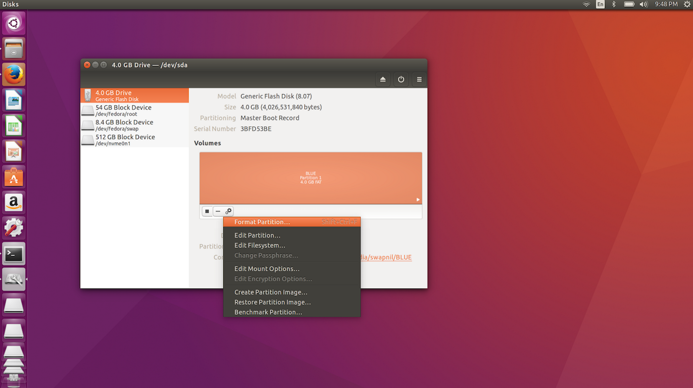
We will be using Linux-based Raspbian as the base operating system for this project. The easiest way to install Raspbian on your Pi is by using NOOBs. Plug in your Micro SD card to your PC and format it as FAT32 using Gnome Disk Utility (Figure 1).
cd /path_of_USB
And unzip the NOOBS file into the Micro SD card:
unzip PATH_OF_NOOBS
In my case it was:
unzip /home/swapnil/Downloads/NOOBS_v1_9_2.zip
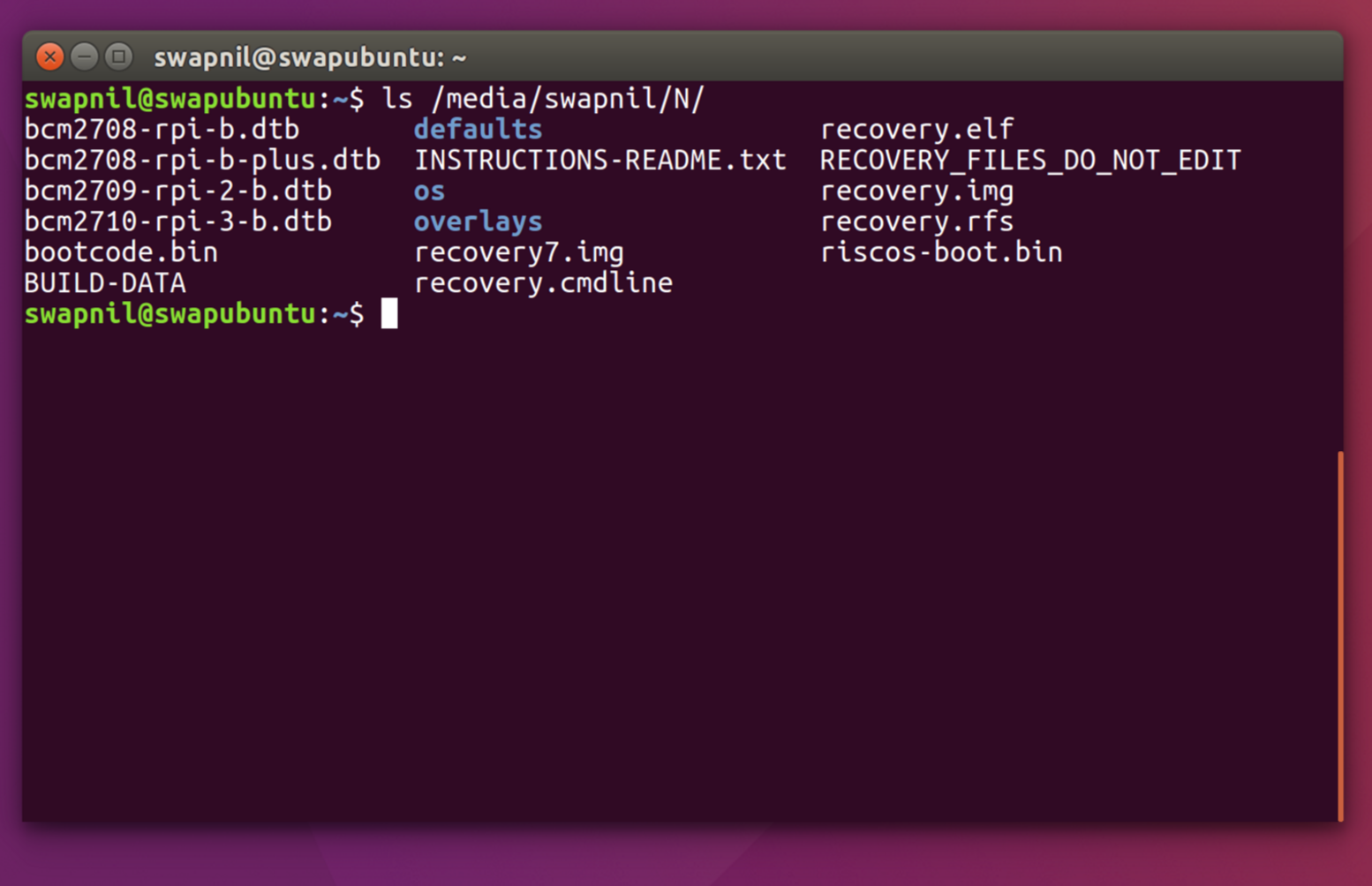
Ensure that all the content of the NOOBS folder is in the root directory of the Micro SD card.
ls /path_of_micro_SD_card/
You should see all these files there (Figure 2):
Prepare your Pi
Connect the Pi to the monitor using an HDMI cable and then connect the keyboard. Connect one end of the GPIO 40 Pin cable to the Pi and the other end to the breadboard using Adafruit Assembled Pi T-Cobbler Plus – GPIO Breakout board. Now plug in the Micro SD card and connect the power supply.
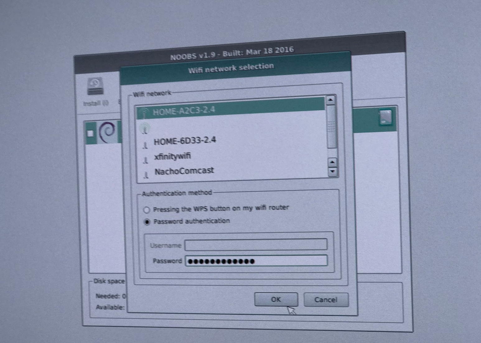
When NOOBS boots, you will see the option to connect to the wireless network. Because we will be using the Rasp Pi outside as a Halloween decoration, we need it to be wireless. Click on the wireless option and select the desired wireless network from the list (Figure 3).
NOOBS will offer several operating systems to choose from, select Raspbian and let the installation finish. Once the installation is finished, reboot the system. Once you boot into Raspbian, update your system:
sudo apt-get update
sudo apt-get dist-upgrade
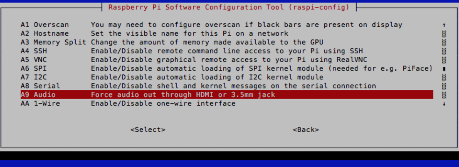
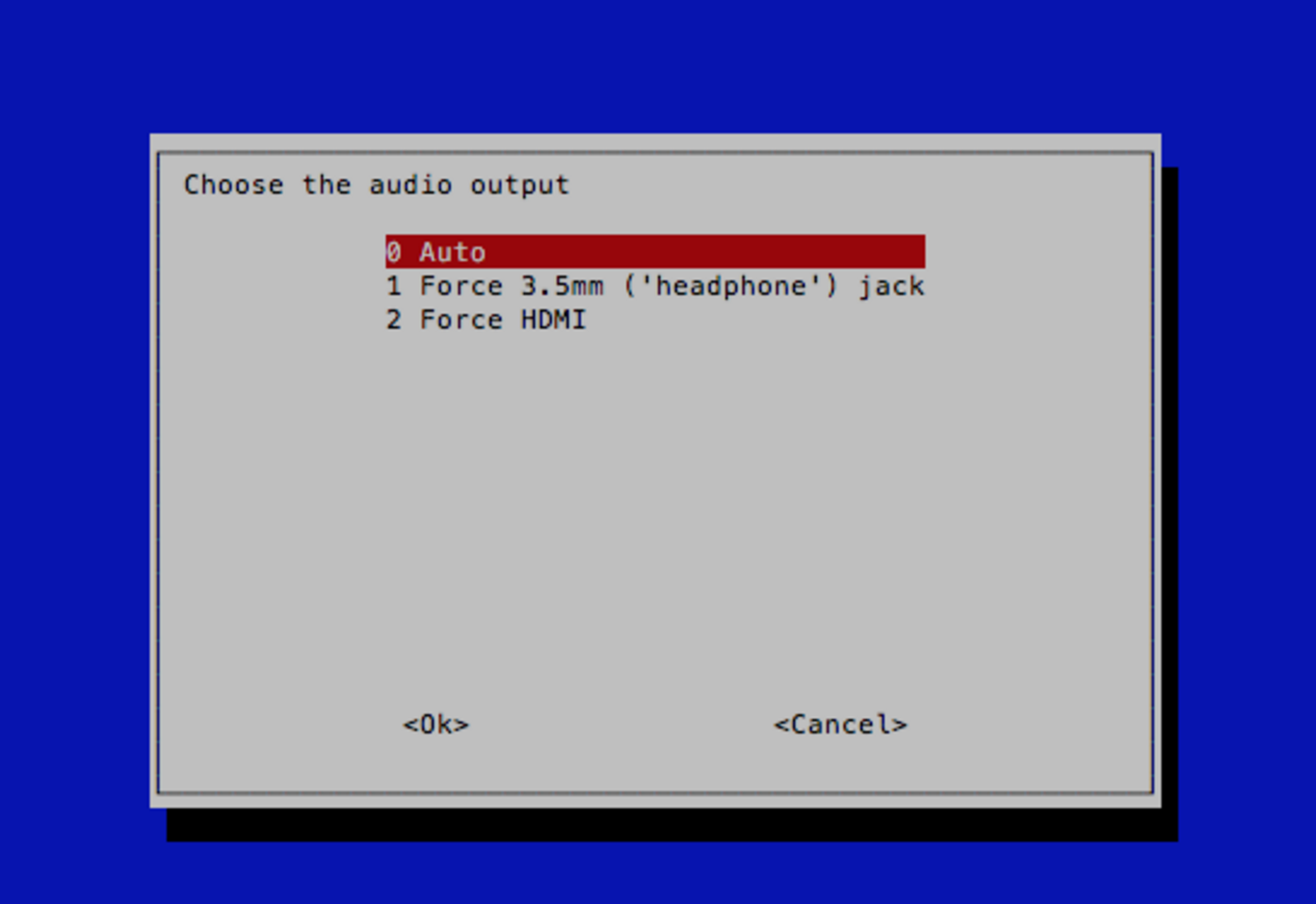
In order to use the sound output from the 3.5mm jack of Raspberry Pi, run the following command to open the configuration file of Raspbian:
sudo raspi-config
Then, go to Advanced>Audio and set audio out from 3.5mm jack (Figures 4 and 5).
Install lightshow software
We are using the open source Lightshowpi project to control music and lights. Clone the project on your local machine:
git clone https://togiles@bitbucket.org/togiles/lightshowpi.git
Change directory to the newly created ‘/home/pi/lightshowpi’ folder:
cd lightshowpi
Grab the stable branch:
git fetch && git checkout stable
Install lightshowpi:
sudo ./install.sh
Reboot the system:
sudo reboot
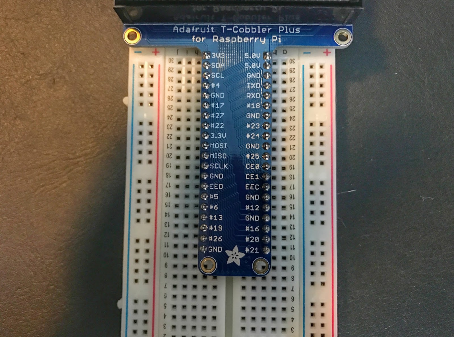
Install LEDs on the Breadboard
We need to set up the LED lights on the breadboard for initial testing. Now we need to find the right PIN of GPIO board for LED connections. I strongly recommend Adafruit’s Assembled Pi Cobbler Plus – Breakout Cable for Raspberry Pi. This cable comes with clearly marked PIN numbers, which will make it easier to connect to each corresponding PIN. Because we are using 8 LEDs for our setup, let’s find out which PINs are we going to use. Figure 6 shows a picture of the Adafruit’s breakout cable.
Each audio channel is represented by a number, starting from 0. Because we are using 8 channels, we have 0,1,2,3,4,5,6,7 channels for each LED. The GPIO pins we are going to use are: #4. #17, #18 #22, #23, #24, #25
Connect the LED for each channel with each GPIO PIN in this way:
|
GPIO |
Channel / LED |
LED |
|
# 17 |
0 |
Red |
|
# 18 |
1 |
Blue |
|
# 27 |
2 |
Green |
|
# 22 |
3 |
Purple |
|
# 23 |
4 |
Yellow |
|
# 24 |
5 |
White |
|
# 25 |
6 |
Orange |
|
# 4 |
7 |
Red |
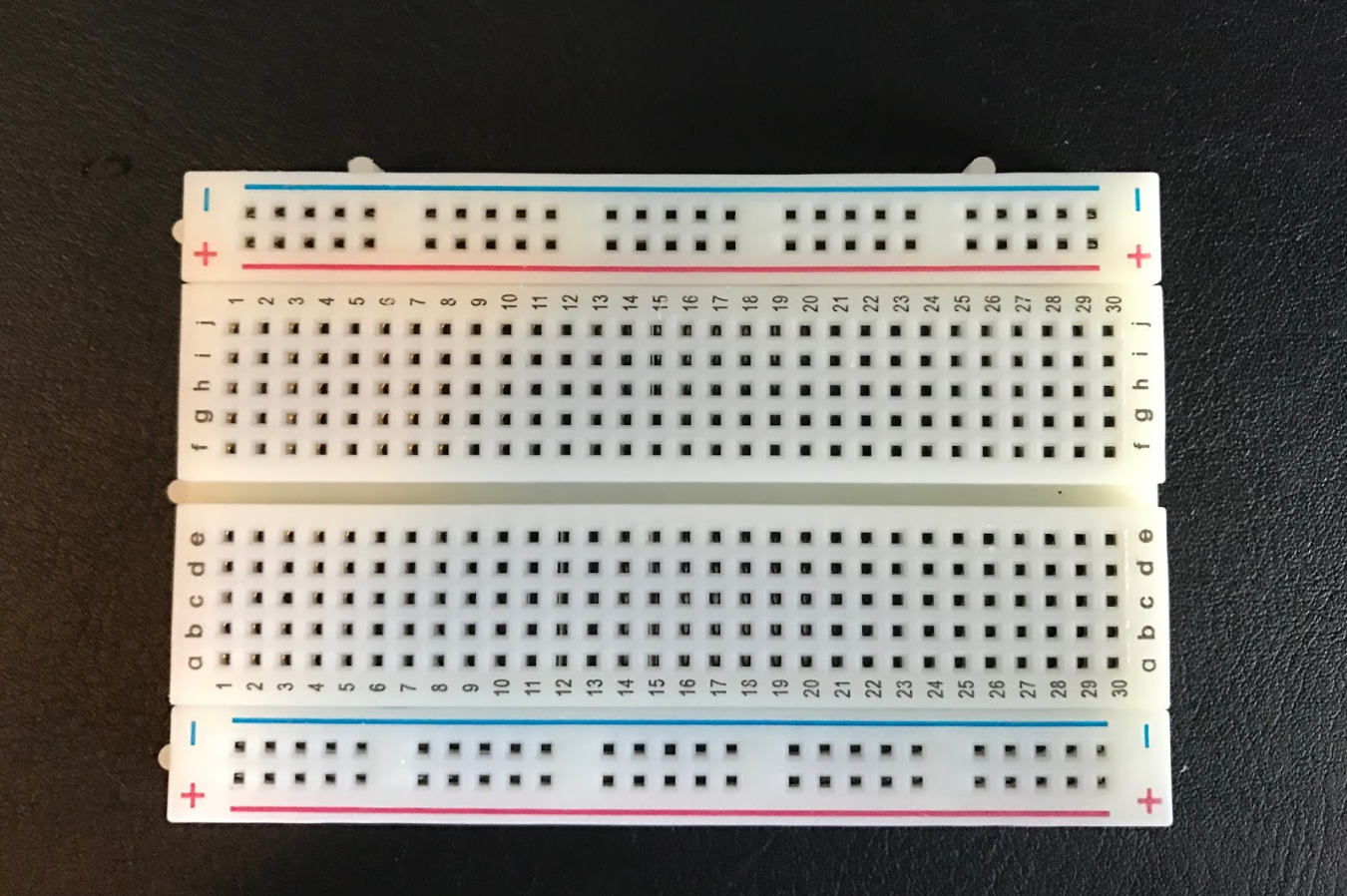
We now need to connect LEDs with the corresponding GPIO pins on the bread board. Figure 7 is a picture of the breadboard.
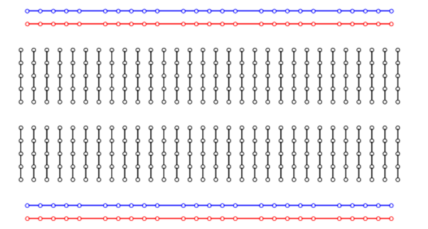
And this is how the holes are connected internally (Figure 8).
We are using 220Ω resistor with each LED and connecting the anode of each LED to the GPIO pins, whereas cathode goes to negative. Here is a simple circuit diagram (Figure 9).
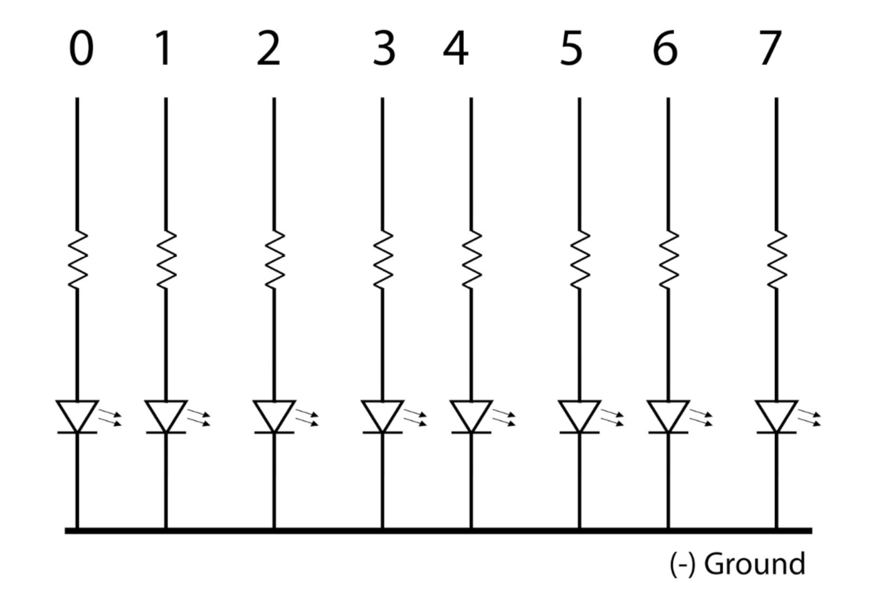
Tip: Long legs of LEDs are anodes, which are connected to positive supply, whereas short legs are cathodes, which are connected to negative supply.
Figure 10 shows the final setup on the breadboard:
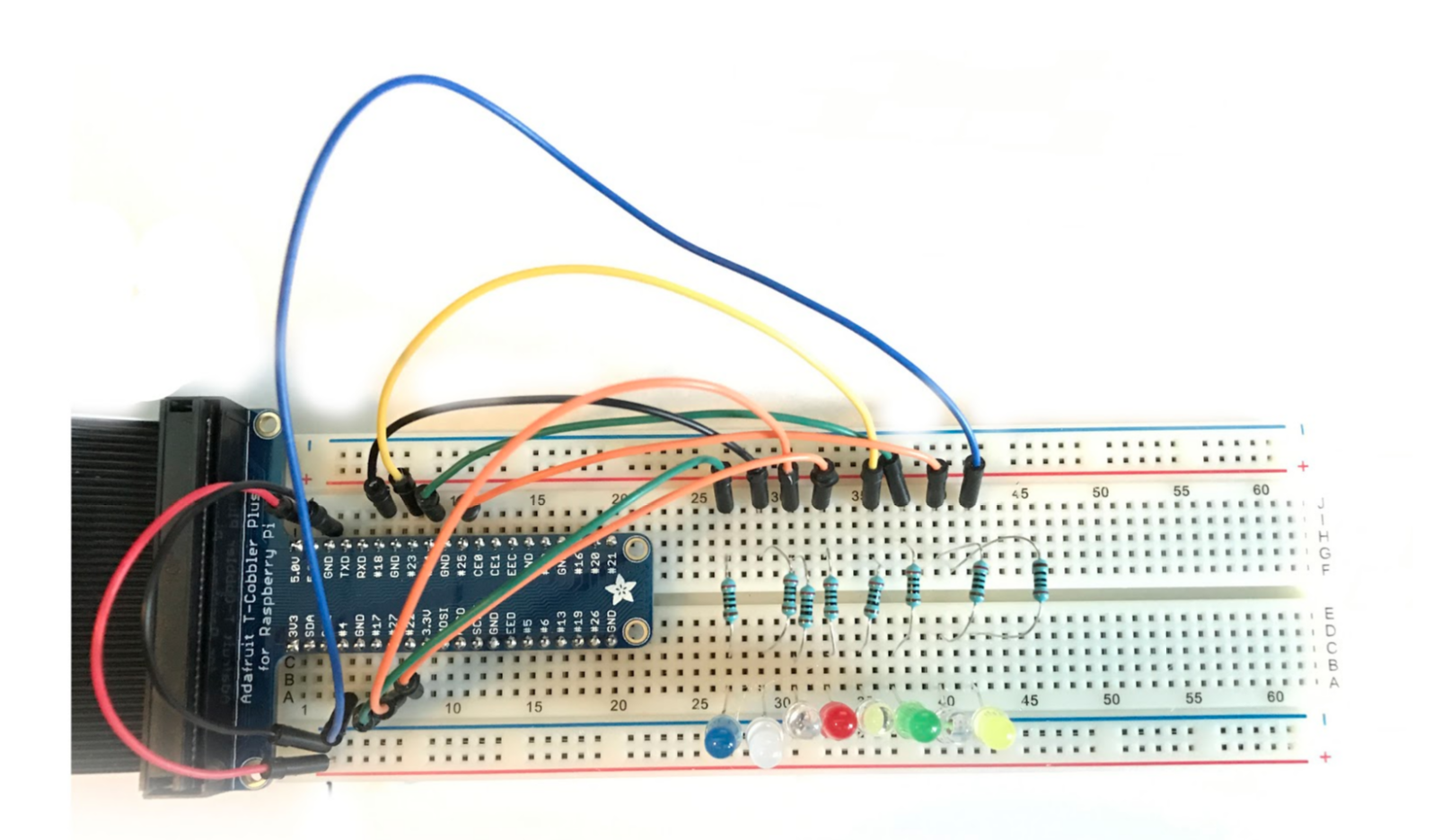
Here you can see +5v (red wire) is coming from the 5v GPIO pin and negative (black wire) coming from the ground pin of GIO, and we plugged these wires into the positive and negative strip on breadboard (blue stripe is negative and red stripe is positive). Then we inserted small legs of the LEDs to the negative strips. We then used wires to connect the GPIO pins with each LED in series with 220Ω resistor. Our circuit is now complete.
Let’s check if the LEDs are working properly. Run the following command (from the lightshowpi directory):
sudo python py/hardware_controller.py --state=flash
You will see the output of each pin number in the terminal and the corresponding LED should blink. If all eight LEDs flash properly, we are on the right track. Exit the command with Ctrl+x or Ctrl+c.
Set up audio
Now let’s test the music-light synchronization. Lightshowpi comes with two mp3 sample files stored in the ‘music’ directory of the lightshowpi folder. Let’s play one of the two files:
sudo python py/synchronized_lights.py --file=/home/pi/lightshowpi/music/sample/ovenrake_deck-the-halls.mp3
If everything is configured correctly, you will get audio output that’s synchronized with the LEDs. You will see different LEDs lighting up responding to different audio frequencies. You can see a video of the setup that I uploaded to YouTube.
Upload your music to the Pi
You can simply copy songs to the music folder of lightshowpi and play the desired songs from the above command, but we are going to use a web-based interface that will allow us to control our Halloween lights from the web browser of our mobile phones. We are going to use webui project to achieve that. The webui script is written by Stephen Burning, which is also available as open source.
First, install some dependencies:
sudo aptitude install python-webpy

sudo pip install glob2
First, fetch the webui package from Git:
git fetch && git checkout webui
Then install it:
./install.sh
(Type A to accept all.)
We need to edit the ‘py/webapp.py’ script to provide it with the IP address of our Pi:
nano py/webapy.py
Go to this line:
Then visit it on your local network (replace with your RPi's IP address):
 http://192.168.X.Y/
And put the IP of your Raspberry Pi there. In my case the IP was ‘http://10.0.0.26/’ so my my file looked like this:
Then visit it on your local network (replace with your RPi's IP address):
 http://10.0.0.26/
Save and close the file and then run the script:
sudo python py/webapp.py
If everything is configured correctly, you will see this output:
http://0.0.0.0:8080/
It works only on the local network, so ensure that your mobile phone is on the same network as is your Pi. Open a web browser on your phone and enter the IP address of your Pi with port 8080:
10.0.0.26:8080
You should see this page (Figure 11):
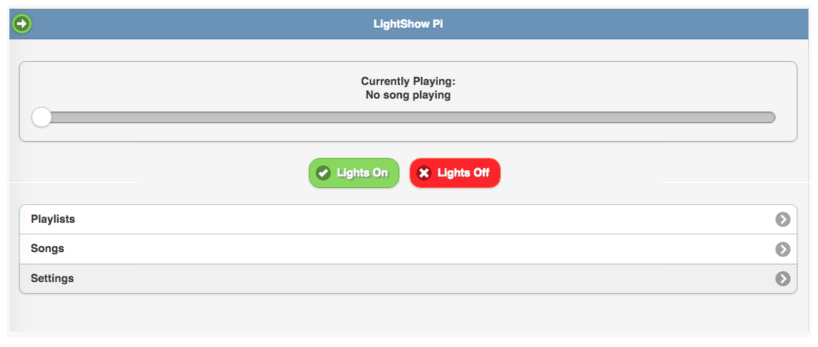
Check if LEDs turn on and off by clicking on those buttons.
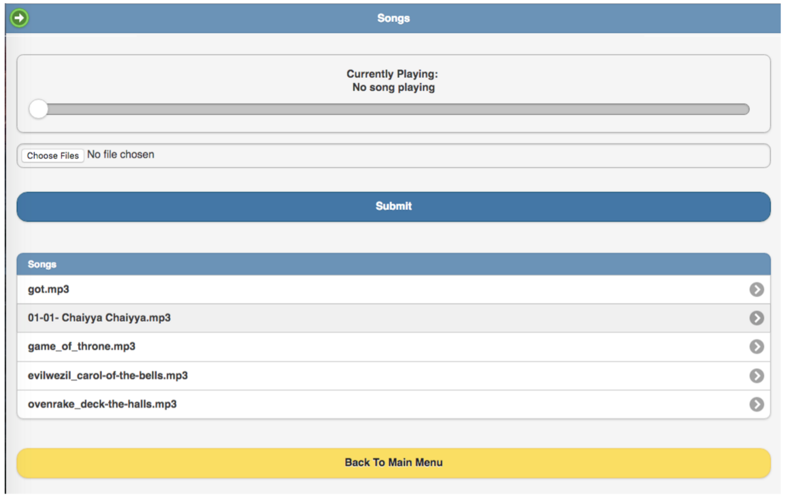
Then, you can click on songs and play your desired song and enjoy a light and music show (Figure 12). You can add more music files to your collection by clicking on ‘choose’ files, which will upload the music files to the music directory of the lightshowpi folder. You can also create a playlist so those songs will play automatically.
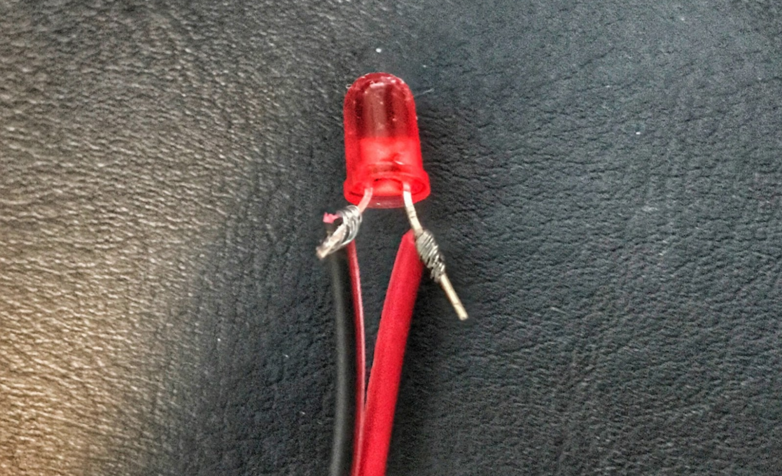
Once the whole setup is complete, you can either put the entire thing inside a ziplock bag and put inside a pumpkin or use long wires to control where you want to install LEDs inside the pumpkin. Just wrap long wire around LED legs and cover it with hot shrink sleeves or electrical tape to avoid shorting (Figure 13).
I used a 5V iPhone battery bank and JBL GO Portable Wireless Bluetooth Speaker to achieve complete mobility. Just make sure that the pumpkin is within the wireless range of your router, so you can manage the song tracks from your phone.
Happy Halloween!
Credit where due
This project is a great example of open source; so many individuals have helped create this amazing experience. The project would not have been possible without the incredible work of Google software engineer Todd Giles and many other individuals have done around the the LightShowPi project. That’s the greatness of open source: you learn and benefit from each other. So, special thanks to Tom Enos, Stephen Burning, Benjamin Ellis, and many more.…
Register now to attend The Linux Foundation’s free webinar on Getting Started with Raspberry Pi, to be held Dec. 14, 2016 at 11 a.m. Pacific.


