
Introduction:
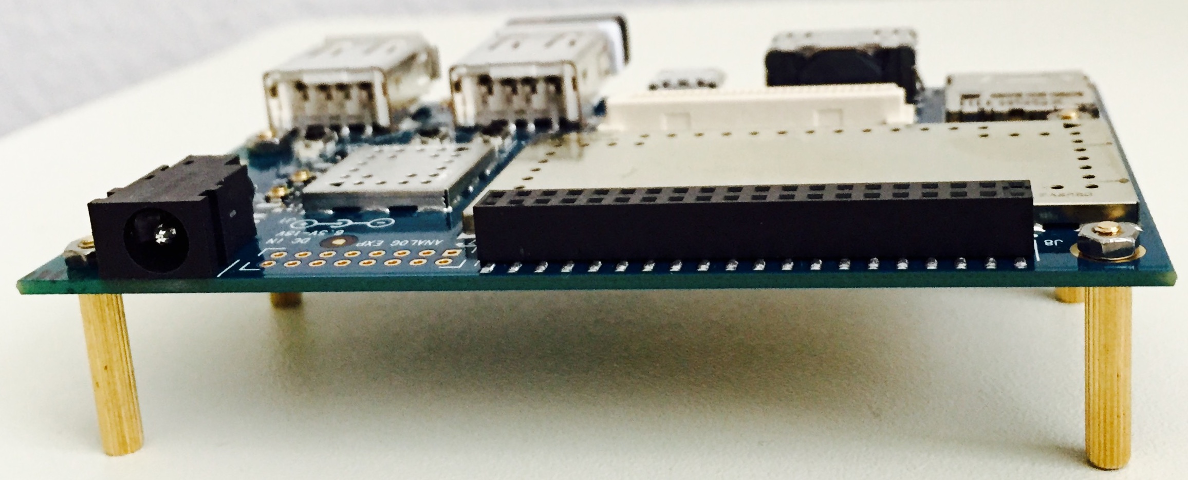
We will use Dragonboard 410c as a development platform for Embedded Linux. Dragonboard 410c from Qualcomm is a powerful piece of hardware based on Quad-core ARM® Cortex® A53 and on board support for Wi-Fi, Bluetooth and GPS. For easy prototyping and development I/O interfaces include UART, SPI, I2S, I2C (2), and GPIO (12). It also supports HDMI interface for display and USB 2.0 for USB devices. For the operating system, it can support Android, Linux, and Windows 10 IoT Core.
It is available for purchase at Arrow for $75 and comes with Android installed.
Setup:
Host machine:
-
Host Machine: We will use Linux based computer (also called host machine) for our development work. The specs of the host machine do not matter as long as it can run Linux, and has access to network. It is possible to develop on Windows/MAC based computers by using Virtual Machine or by using dual boot. My workstation has Ubuntu 16.04 LTS
-
IDE: Eclipse CDT on the host machine
-
-
Micro USB cable
-
Micro SD card (minimum of 4GB) and a SD card reader.
-
HDMI to DVI cable or if monitor supports HDMI then HDMI to HDMI cable.
-
Access to network
-
A spare monitor and spare keyboard/mouse – If not available; when connecting to Wi-Fi, borrow from host machine.
-
Static mat (optional): It is always good to protect the HW from static so a static mat will help
Prepare the Dragon:
Dragonboard comes with Android installed. For our development, we will install Linux provided by Linaro. Make sure you have su rights on the host machine. Connect the micro USB cable to host machine and the dragonboard.
-
Install fastboot
sudo apt-get install android-tools-fastboot
-
Download the necessary images from 96boards.org
-
Extract all the above images (either use tar or use right click-> extract here)
-
Bring the target into fastboot
-
Set the switches on S6 to 0-0-0-0
-
Connect the micro-usb to target and host machine.
-
With Vol(-) button (S4) pressed, power up the board.
-
-
On the host machine, check for fastboot devices
sudo fastboot devices
-
Once the device shows up in fastboot, run the following commands
-
Flash the boot loader image from dragonboard410c_bootloader_emmc_linux-BB
-
sudo fastboot flash partition gpt_both0.bin fastboot flash hyp hyp.mbn

sudo fastboot flash modem NON-HLOS.bin fastboot flash rpm rpm.mbn

sudo fastboot flash sbl1 sbl1.mbn

sudo fastboot flash sec sec.dat

sudo fastboot flash tz tz.mbn

sudo fastboot flash aboot emmc_appsboot.mbn

sudo fastboot erase boot

sudo fastboot erase rootfs

sudo fastboot erase devinfo
-
Flash the boot image
sudo fastboot flash boot
       boot-linaro-jessie-qcom-snapdragon-arm64-YYYYMMDD-UU.img
-
Flash the rootfs image
sudo fastboot flash rootfs
       linaro-jessie-alip-qcom-snapdragon-arm64-YYYYMMDD-UU.img
Power cycle the target and you should boot in Linux. It automatically logins as user: linaro.
Make note of the user and password as they will be used in future.
User: linaro
Password: linaro
Setup Wi-Fi on the dragonboard:
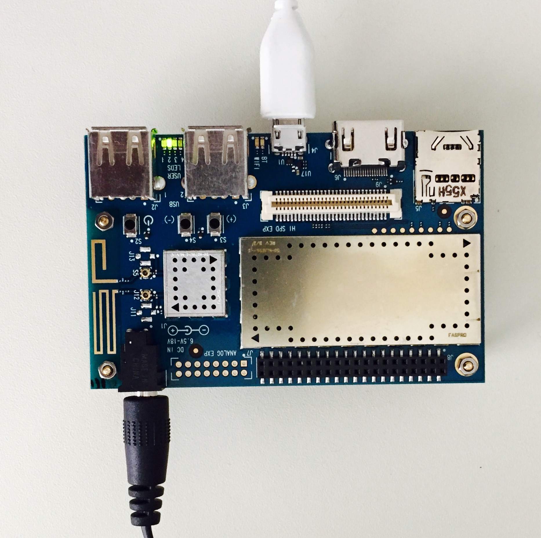
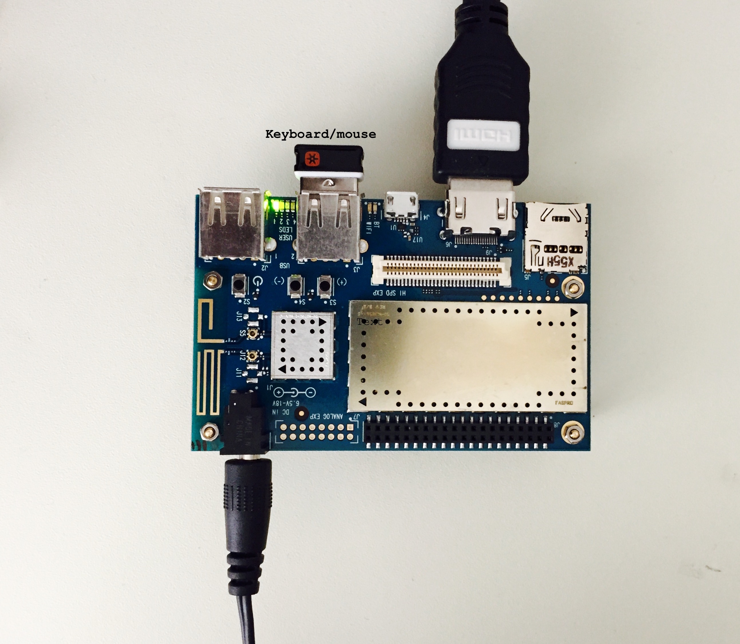
Disconnect the micro USB cable and connect monitor and keyboard/mouse (borrow from host machine if you don’t have spare).
-
Go through the GUI and setup Wi-Fi
-
Ping an external website to make sure Wi-Fi is connected and works as expected.
-
Ping host machine and make sure it is successful.
-
(ifconfig does not work on target, so use ip addr to get the ip address of the target)
-
Ping target from the host machine.
Once you have the IP address of the target, you could SSH and communicate with the target.
ssh linaro@<target IP address>
Connect through SSH and play around with some basic commands. Navigate around your home directory and check the contents.
You can transfer the applications from host machine to target using a flash drive but it is not convenient. And it is not easy to debug the applications on target this way. We want to have a seamless way to share applications between host and target.
Setup NFS (Network File System):
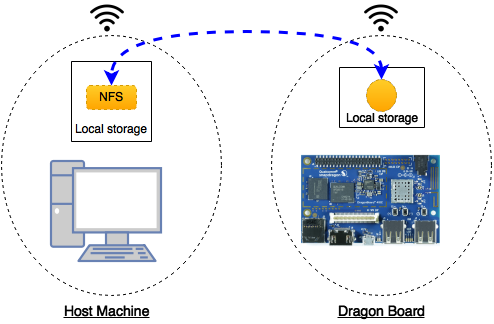
We will create a space on the host machine and share it. On the target, we will mount this space. This will be a common shared space between host and target. Any files created either from the host or the target in this shared space will be visible to both host and target.
Host Machine:
-
Check for firewall settings – disable if any.
-
Note down host IP address and mask info (ifconfig should get this info)
-
Install NFS server application (more info in the link below)
sudo apt-get install nfs-kernel-server
-
Create a folder that will be shared with the target
-
For example: /home/<user>/Dragonboard/Projects
-
Make it read/write/executable:
-
chmod a+rwx /home/<user>/Dragonboard/Projects
-
Configure the server (this will make the folder visible to the network)
-
Edit the exports file in /etc folder (use sudo)
-
Either vim or gedit should work
-
Add the following line to the file
<path_of_the_folder_created_above> <base_of_network_of_host>/<mask> (rw,sync,no_subtree_check)-
If your IP address is 192.168.1.64 then the base is 192.168.1.0
-
-
-
Restart/start the NFS server
-
Ensure that the folder is indeed exported using
showmount -e
If you see the folder in the export list then your host is setup for NFS.
Target (Dragonboard):
Target needs some work and some new applications to install. All the below installations are to be done on target.
You can use SSH or use a keyboard/mouse with monitor connected to dragonboard. I recommend SSH as you will get used to the command line and this will also ensure that SSH is working reliably.
Install BusyBox on the target:
-
Download the latest version from the busybox.net or its git (https://git.busybox.net/)
-
At the time this was being written, 1.24 was the stable version. Follow the instructions here to install 1.24
-
On my setup, for some reason the busybox did not get copied to /usr/bin. I had to manually copy it from /install from busybox folder (download location)
-
Once you have the busybox installed, execute the following command to mount the host NFS onto the target (all this is in one line)
busybox mount -o tcp -t nfs -o nolock
         <server_ip_addr_here>:<absolute_path_of_shared_folder_on_server>
         <mount_location_on_target>
-
For example: busybox mount -o tcp -t nfs -o nolock 192.168.1.64:/home/basu/Dragonboard/Projects /Projects
-
You can save the command into a script for easy execution
echo <busy_box_command_above> > mount_my_nfs
-
Make it executable
chmod +x mount_my_nfs
-
And run when needed
./mount_my_nfs
Instead of executing it every time you reboot the target, you can schedule a cron job. You can install cron on target and add @reboot job for the above script. There are other ways to do the same. Explore them and pick one, it will save you time.
If all goes well, you should have a NFS working between your host and target. Make some changes on your host folder (add a file/folder), it should show up on the target. Similarly, make changes from the target side and the change should reflect on the host location.
Static v/s dynamic IP:
Depending on your router, everytime you boot, you may get the same IP for both host and target. But if your IP happens to change, please consider using static IP for both host and target.
Cross Compiler:
From wiki (https://en.wikipedia.org/wiki/Cross_compiler):
A cross compiler is a compiler capable of creating executable code for a platform other than the one on which the compiler is running. A cross compiler is necessary to compile for multiple platforms from one machine. A platform could be infeasible for a compiler to run on…
So we need to get cross compiler toolchain that generates executables for the dragonboard. Linaro has provided the tool chain for the dragonboard (It is probably possible to use other arm toolchains, but I haven’t looked at them yet).
-
Download the toolchain from the below location (note: download binaries). If you want to try the latest version, go for it. Should not be an issue.
-
Extract it in your preferred folder.
-
FYI: I have created a folder for dragonboard in my home directory, where I have all the items related to dragon board (documents, images, etc…). My toolchain is inside this folder <home>/dragonboard/toolchain/<linaro toolchain>
-
-
Add the bin path to the system path. Your system path should have this <home>/dragonboard/toolchain/<linaro toolchain>bin
-
This article might be come handy: https://help.ubuntu.com/community/EnvironmentVariables#System-wide_environment_variables
-
-
Make sure path is updated by echoing path.
-
You may need to logout and login for the new path to take affect.
-
Hello World, from the Dragonboard!
As a tradition, we will start with a simple Hello World program. This will allow us to verify the following:
-
NFS – which should already be verified
-
SSH between host and target
-
More importantly the cross tool chain. We need to build an executable that is compatible with the dragonboard.
-
Execute on the board.
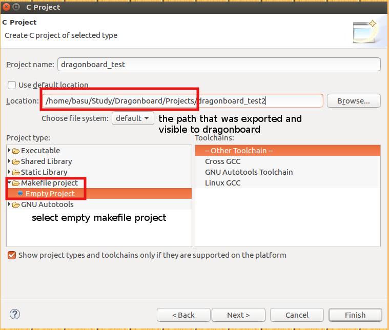
Eclipse project:
-
Create a new makefile project as shown in the screenshot below.
-
Note the location of the project – this is the folder that is exported to dragonboard.
-
-
Add a new source file (.c) and a Makefile (just add new file) with contents shown below.
-
Some information on the Make – http://web.mit.edu/gnu/doc/html/make_toc.html
-
Source code:
#include <stdio.h>
#include <stdlib.h>

int main(void)
{

	printf("Hello World!, this is Dragonboard.n");
	return 0;
}
-
Build using Make (Shift + F9).
#  make all - build dragonboard_test
#  make dragonboard_test - build dragonboard_test
#  make clean - clean

CC = aarch64-linux-gnu-gcc

all: dragonboard_test

dragonboard_test: dragonboard_test.c
	${CC} -o $@ $<

clean:
	rm -f *.o
	rm -f dragonboard_test
If all goes well, you should have executable in the project folder.
Execute on target:
-
You should see the executable on the NFS mounted location on the dragonboard.
-
Execute the application.
./dragonboard_test
-
You should see hello message on the console. See screenshot below (I am using PuTTY for SSH).
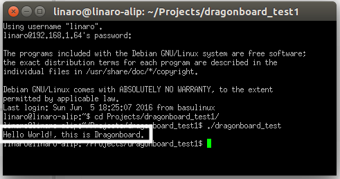
Congratulations! On your first program on dragonboard.
Blinking LED:
Just like Hello World program for any C programmer, blinking a LED should be a first program for any embedded engineer. In this chapter, we will blink one of the user LEDs on the dragonboard.
The dragonboard has 4 user defined LEDs. LED1 is used for heartbeat and we will cover it later. For now, we will skip that. We will make use of LED2 in our program.
Method 1: Memory mapping
Note: This is not the recommended way, but this will give an opportunity to look into GPIO registers.
Before we get into the program, lets look at the registers that control the LED. It is connected to APQ GPIO 120.
From DragonBoard_HardwareManual_v5:
The four user LEDs are surface mount Green in 0603 size located next to the two USB type A connector and labeled ‘USER LEDS 4 3 2 1’. The 410c board drives two LEDs from the SoC GPIO, APQ GPIO_21 and APQ GPIO_120. The other two User LEDs are driven by the PMIC via PM GPIO_1 and PM GPIO_2.
From chapter 7 of lm80-p0436-5_e_peripherals_programming_guide:
Each MSM/MDM/APQ chipset has a dedicated number of GPIOs that can be configured for multiple functions. For example, if you check the GPIO mapping for MSM8916 GPIO 0, you will see that the GPIO can be configured as one of the following functions at any time:
-
Function 0 – GPIO
-
Function 1 – BLSP1 SPI MOSI
-
Function 2 – BLSP1 UART TX
-
Function 3 – BLSP1 User Identity Module (UIM) data
-
Function 4 – HDMI_RCV_DET
GPIO_CFGn controls the GPIO properties, such as Output Enable, Drive Strength, Pull, and GPIO Function Select.
Physical Address: 0x01000000 + (0x1000 * n) = GPIO_CFGn
|
Bit |
Definition |
Notes |
|
31:11 |
|
Reserved |
|
10 |
GPIO_HIHYS_EN |
Control the hihys_EN for GPIO |
|
9 |
GPIO_OE |
Controls the Output Enable for GPIO |
|
8:6 |
DRV_STRENGTH |
Control Drive Strength |
|
5:2 |
FUNC_SEL |
Make sure Function is GSBI. |
|
1:0 |
GPIO_PULL |
Internal Pull Configuration 10:Keeper 11: Pull Up |
*The configuration register is already programmed to the correct settings.
GPIO_IN_OUTn controls the output value or reads the current GPIO value.
Physical Address: 0x01000004 + (0x1000 * n) = GPIO_IN_OUTn n = GPIO #n
|
Bit |
Definition |
Notes |
|
31:2 |
|
Reserved |
|
1 |
GPIO_OUT |
Control value of the GPIO Output |
|
0 |
GPIO_IN |
Allows you to read the Input value of the GPIO |
The code is pretty straight forward:
-
Open a memory device
-
Memory map the above register address using mmap
-
Note from man page: offset must be a multiple of the page size as
returned by sysconf(_SC_PAGE_SIZE).
-
-
Enter an infinite loop (until aborted) which toggles the LED
-
Note that we are not programming the configuration register as it is already programmed.
-
Recommend printing the configuration value and mapping it to the above table.
-
-
When abort is called, we clean up and exit.
Source code:
/*
 * led.c
 *
 *  Created on: Jun 10, 2016
 *      Author: basu
 */


#include <stdio.h>
#include <stdlib.h>
#include <string.h>
#include <errno.h>
#include <unistd.h>
#include <fcntl.h>
#include <signal.h>
#include <sys/types.h>
#include <sys/mman.h>

#define ERR_FATAL do { fprintf(stderr, "Error: file %s, line %d, error (%d) [%s]n",
		__FILE__, __LINE__, errno, strerror(errno)); exit(1); } while(0)

typedef struct
{
	unsigned int cfg;            /*place holder for configuration register*/
	unsigned int in_out;				 /*place holder for IO register*/
}db_gpio_type_s;

int abort_program = 0;

/*GPIOn physical address = 0x01000004 + (0x1000 * n); ref: e peripherals programming guide*/
unsigned int GPIO_120_CFG_ADDR = 0x01000000 + (0x1000 * 120);
unsigned int GPIO_120_IO_ADDR = 0x01000004 + (0x1000 * 120);

void stop_program(int sig)
{
	abort_program = 1;
}

int main(int argc, char *argv[])
{

	db_gpio_type_s *gpio_120;
	int fd_mem;

	/*initialize signal to abort the program*/
	signal(SIGINT, stop_program);

	fd_mem = open("/dev/mem", O_RDWR | O_SYNC);

	if (fd_mem < 0)
	{
		printf("Failed to open /dev/mem. Abortingn");
		ERR_FATAL;
	}

	gpio_120 = (db_gpio_type_s *)(mmap(0, sizeof(db_gpio_type_s), PROT_READ | PROT_WRITE, MAP_SHARED, fd_mem, GPIO_120_CFG_ADDR));

	if (gpio_120 == (void *)-1)
	{
		printf("Failed to map GPIO address. Abortingn");
		close(fd_mem);
		ERR_FATAL;
	}

	while (!abort_program)
	{
		gpio_120->in_out = gpio_120->in_out | 0x02;
		printf("Contents of physical address 0x%X is 0x%Xn", GPIO_120_IO_ADDR, gpio_120->in_out);
		sleep(1);
		gpio_120->in_out = gpio_120->in_out &; ~0x02;
		printf("Contents of physical address 0x%X is 0x%Xn", GPIO_120_IO_ADDR, gpio_120->in_out);
		sleep(1);
	}
	/*clean up and exit*/
	gpio_120->in_out = gpio_120->in_out & ~0x02;

	if (munmap(gpio_120, sizeof(int)) == -1)
	{
		printf("Failed to unmap GPIO address. Abortingn");
		close(fd_mem);
		ERR_FATAL;
	}

	printf("Contents of physical address 0x%X is 0x%Xn", GPIO_120_IO_ADDR, gpio_120->in_out);

	close (fd_mem);
	printf("nProgram exitingn");
	return 0;
}
If all goes well, execute the program and you should see the LED2 blinking. You may have to run as SUDO to get permission to open a device.
Method 2: Using /sys files
Using /sys files to control LEDs is very simple. For explanation on using sys files, please refer to kernel documentation
https://www.kernel.org/doc/Documentation/leds/leds-class.txt
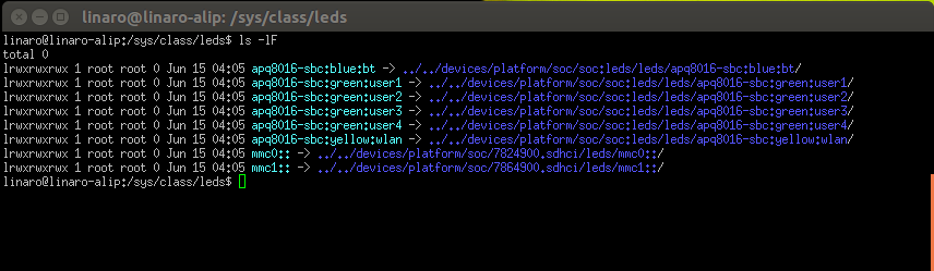
Under /sys/class/leds, try the following
ls -lF
This will list all the LEDs on the dragonboard as shown in the screenshot below
The code again is straight forward:
-
Open the brightness file
-
Write “1” to turn LED ON
-
Write “0” to turn LED OFF
-
Close the file and exit
Source code:
/*
 * led_sys.c
 *
 *  Created on: Jun 13, 2016
 *      Author: basu
 */


#include <stdio.h>
#include <stdlib.h>
#include <string.h>
#include <errno.h>
#include <signal.h>
#include <fcntl.h>
#include <unistd.h>


#define ERR_FATAL do { fprintf(stderr, "Error: file %s, line %d, error (%d) [%s]n",
		__FILE__, __LINE__, errno, strerror(errno)); exit(1); } while(0)

int abort_program = 0;

/*file system for LED 2*/
#define LED2 "/sys/class/leds/apq8016-sbc:green:user2/brightness"

void stop_program(int sig)
{
	abort_program = 1;
}


int main(int argc, char *argv[])
{
	int fd_led2;
	/*open the file*/

	/*initialize signal to abort the program*/
	signal(SIGINT, stop_program);

	printf("%sn", LED2);

	fd_led2 = open(LED2, O_WRONLY);

	if (fd_led2 < 0)
	{
		ERR_FATAL;
		return 1;
	}

	while (!abort_program)
	{
		write(fd_led2, "1", 2);
		sleep(1);
		write(fd_led2, "0", 2);
		sleep(1);
	}

	/*clean up and exit*/
	write(fd_led2, "0", 2);

	close (fd_led2);
	printf("nProgram exitingn");
	return 0;

}
Debugging using Eclipse:
Debugging is an important step in development. Even though, we can simulate the target HW behavior and exercise most of our code, there are times where debugging with the application running on the target becomes very critical. As a embedded developer, we should execute/debug our program on the HW and make sure it behaves as expected.
Eclipse and gdb make it easier to debug programs on the target.
We will use gdbserver to debug our program on the remote target.
From the man-pages:
gdbserver is a program that allows you to run GDB on a
different machine than the one which is running the program being debugged.
Refer to the link here for more information on gdbserver
(https://ftp.gnu.org/old-gnu/Manuals/gdb-5.1.1/html_node/gdb_130.html)
Follow the steps below to step through your program. We will use the blinking LED from the previous chapter as an example.
-
Make sure you can build the program and is visible on the target.
On the target:
-
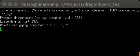
On the target, execute the following
sudo gdbserver :2000 dragonboard_led_sys
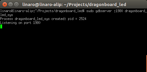
-
This will start the process and will start listening on port 2000 for the remote debug to begin. This number can be anything > 1023.
On the host machine (inside Eclispe):
-
We need to configure eclipse to communicate with the target using gdbserver
-
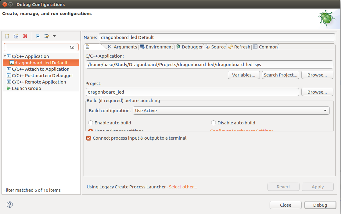
Select the application (shown in the screen shot below):
-
In the project navigator, right click on the LED project and select Debug As -> Debug Conjurations
-
On the main tab, Select C/C++ Application and point to the LED program executable (You have to browse to the project and manually select it).
-
-
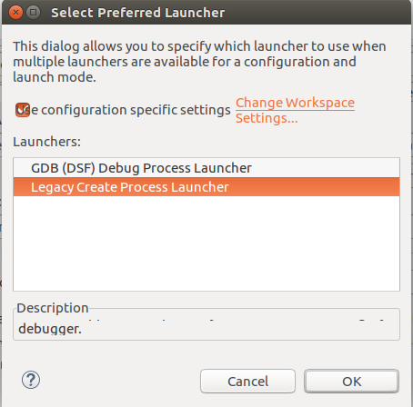
Select the Preferred Launcher (shown in the screen shot below):
-
Select other for the Using Debug Process Launcher.
-
On the new pop-up window, select Legacy Create Process Launcher.
-
-
-
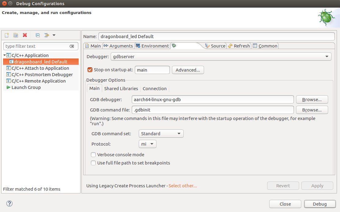
Select the debugger (shown in the screen shot below):
-
On the debugger tab, select gdbserver for the debugger.
-
Stop at main on startup.
-
GDB debugger: aarch-linux-gnu-gdb (this is our dragonboard debugger)
-
On the connection sub-tab, select TCP for the type of connection
-
Enter the target IP address (dragonboard IP address)
-
Enter 2000 for the port number. Or any number you choose while executing on dragonboard.
-
-
Click Debug.
-
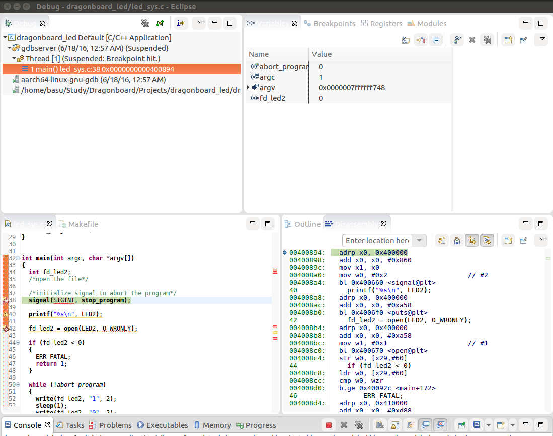
This should open up a new debug perspective for the application (shown in the screenshot below).
-
The execution will be stopped at main and waiting for you to continue
-
Spend sometime on the perspective.
-
Take a look at variable pane, debug pane, breakpoints, disassembly, etc …
-
On the target you should see a remote debugging from host (host IP address) printed. It’s a very small program, so we can just hit F6 and step through.
There you have it, you are remote debugging your program on directly on the target.
Debugging on the target machine is very important and sometimes there are no alternatives but to debug live. Eclipse and gdb make it easier!
-
Insert the SD card into host machine.
-
Instead of command line options, use the startup disk creator tool to write rescue image on the SD card.
-
Disconnect the power from the target.
-
Insert the rescue SD card into the target.
-
Set the switches on S6 to 0-1-0-0
-
Power up the target.
-
You should detect device in fastboot.
-
Once images are loaded, remove the SD card and power cycle the target
-
It is OK to leave the switches in 0-1-0-0 position with no SD card. The switch positions determine the boot order and when SD card is not detected, it will fall back to eMMC.
-
References:
-
NFS on Ubuntu: https://help.ubuntu.com/community/SettingUpNFSHowTo


