In this two-part series we are are going to build a cool Arduino device that plays sounds triggered by a motion detector. I’m sure you can think of many applications for this: visitor alerts, scaring cats off kitchen counters, sound an alert when you fall asleep in your chair and tip over, cubicle invasion alarm…
(Part 2 is available at Building an Arduino Pest Repeller on Linux (Part 2))
I like it for protecting my garden from hungry pests. Out here in my little corner of the world we humans occupy 5 percent of the county. The fat deer, skunks, raccoons, and all the rest of the local animal kingdom that love my garden can jolly well dine elsewhere.
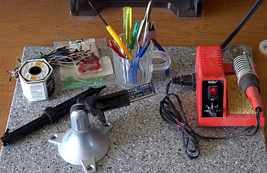
Arduino is both an open embedded hardware platform, and an open software platform. It is a wonderful introduction to embedded programming, electronics, robotics, and rapid prototyping. To complete this project you must know how to solder and de-solder, and how to read a schematic. If you are new to electronics and Arduino, then you should study these first:
Weekend Project: Learning Ins and Outs of Arduino
Weekend Project: Loading Programs Into Arduino
Arduino Tutorial
Arduino Lesson 1. Blink
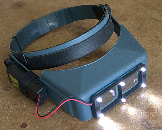
Shopping List
There are many online shops full of fun Arduino gear. I shop at Adafruit Industries, Jameco, Sparkfun, and Digikey. Adafruit is an exceptionally good resource full of great gear, tutorials, and product documentation. About $250 buys everything you need for this project, including tools and solder. If you already have tools your materials cost is under $100. You need:
- Arduino Uno
- WAVE shield for Arduino, plus an SD card and speaker. Speakers salvaged from PCs or laptops work great
MaxBotix LV-EZ1 Ultrasonic Range Finder
If you buy a starter pack you get useful extras. It is always good to have extra stuff.
The WAVE shield comes un-assembled so you’ll need to put it together. A common problem is knowing where to solder your speaker wires. If you study the WAVE board schematic you see that the speaker output is the two pins immediately behind the headphone jack. In figure 3 you see black and red speaker wires soldered to the speaker pins. It doesn’t matter which wire goes on which pin.
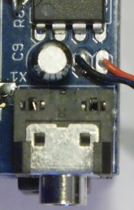
Or you may omit the speaker and use the headphone jack instead, using an adapter to attach a speaker. The speaker output pins deliver a whopping 1/8 Watt into 8 ohms or 1/4 watt into 4 ohms. The headphone jack has a slightly more powerful output. You’ll have to pipe your output through an external amplifier to get any significant volume with either one. You can get a usable volume level for indoor use by carefully pressing a second TS922 amplifier chip on top of the existing one on your WAVE shield.
Note that the WAVE shield only plays mono 16-bit 22050 MHz WAV files, and your SD card should be formatted in FAT16 or FAT32.
Testing Playback
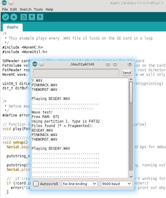
Download the WaveHC library and unpack it into /usr/share/arduino/libraries/. You can test your nice WAVE board with the daphc.pde sketch which is included in the WaveHC library. This sketch plays every WAV file on your SD card and prints the filenames in the Arduino IDE serial monitor. So, obviously, you’ll need some audio files loaded on your SD card. Carefully attach the Wave shield to the Arduino. Connect the Arduino to your computer, load the daphc.pde sketch (File > Examples > WaveHC), and if it plays, hurrah! Open the Serial Monitor to see the messages as the sketch runs (figure 4). If it doesn’t then you get to practice troubleshooting.
Attaching the MaxBotix Sonar Rangefinder
The MaxBotix is more than a simple motion detector; it is a sonar rangefinder with a range of 6 to 254 inches. It emits a high-frequency (42kHz) sound and measures the length of time it takes for an echo to bounce back. This measurement is by voltage, so the higher the voltage the farther away the 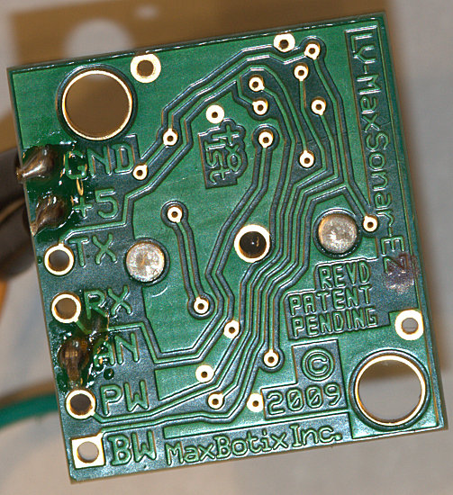 object. This isn’t a super-precision rangefinder, but it is accurate enough for our purposes. The EZ1 has a narrow directional detection beam. The other Maxbotix sonar rangefinders have even narrower detection ranges.
Grab your soldering iron and connect some wires to the GND, +5, and AN pins on the EZ1 (figure 5).
Disconnect your Arduino from your PC and detach the WAVE shield from your Arduino. Connect the GND wire on the EZ1 to GND on the WAVE shield, +5 to +5, and AN to Analog In #0 (figure 6). GND is the ground wire, and +5 is the 5-volt power supply. The WAVE shield has 6 analog input pins, which are passthroughs to the Arduino board. These are analog-to-digital (A/D) converters, and are used to read analog sensors. They can also be used for general-purpose input and output (GPIO).

Now let’s test the EZ1 with this simple sketch:
// ez1_measure.ino; print in inches
// how far away objects are
    void setup() {
    Serial.begin(9600);
    }
    void loop(){
    float a0value = analogRead(0);
    float inches = 0.496 * a0value;
    Serial.print("The value captured from pin a0 is: ");
    Serial.println(a0value);
    Serial.print("The distance in inches is ");
    Serial.println(inches);
    delay(3000);
    }
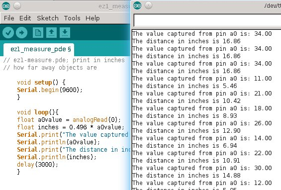
Load this sketch and hold objects in front of the sensor at different distances, and you’ll easily see how accurate it is. It should be within an inch or so (figure 7).
The EZ1 QuickStart Guidedescribes the math used to convert voltage to a distance measurement. But using the formula in the QuickStart Guide isn’t enough, because the EZ1 uses a 9-bit factor, and the Arduino’s A/D converter is 10-bit. The 9-bit equation looks like this:
(5.0V/512) = 0.009766V per inch * 1000 = 9.766mV per inch
The 9-bit formula divides the voltage by the maximum binary value (9 bits = 29 = 512), and then I multiply by 1000 to convert those itty bitty fractional volts to millivolts because it’s easier to read.
So how to convert to 10-bit? Multiply by two, because one more bit is 210 = 1024. So the conversion to 10-bit divides the volts by the maximum binary value of 1024 bits, then multiplies by two to get the equivalent 9-bit value, and then the conversion to millivolts:
(5.0V/1024) * 2 = 0.009765625V per inch = * 1000 = 9.765mV per inch
How to convert this to inches? Take the maximum range of the EZ1, 254 inches, divide by the maximum digital value, 1024, multiply by two, and then we have 0.496. Then multiply 0.496 by the value captured from the Analog Pin #0, and you have a distance measurement in inches.
That is a good start for this project, so we are stopping here. See part two for the full Arduino sketch and final details on setting up the device.


