We’re going to build an Arduino reminder machine with an Arduino Uno, MaxBotix EZ1 sonar rangefinder, WAVE shield, and the DS1307 real-time clock. This builds on our previous project, How to Build an Arduino Pest Repeller on Linux. When you walk by the MaxBotix it will trigger the WAVE shield to play scheduled audio reminders. Or read poems, or play music, or anything you want. It also includes a timeout so it doesn’t drive you crazy playing the same reminder over and over.
See part 2 here.
In part 1 this week we’ll learn about solderless breadboards and the DS1307 real-time clock for keeping time on Arduino devices. In part 2 we’ll load and test the complete sketch.
Serial Speed Detection
The serial speed in the example sketches is 9600. It may be different on your system, and if there is a mismatch your Arduino IDE serial monitor will display garbled characters. Use the stty command to find your serial port speed:
$ stty -F /dev/ttyACM0 speed
9600
Prerequisites
Please review How to Build an Arduino Pest Repeller on Linux, as this project builds on it. You must have a basic electronics toolkit, know how to solder and assemble Arduino components, and know how to find and read the instructions and specifications for the various components. Adafruit Industries, Jameco, Sparkfun, and Digikey are all good places to buy Arduino gear. You need these items for this project:
- Arduino Uno or any newer Arduino board based on an Atmega328 or better
- WAVE shield
- MaxBotix LV-MaxSonar-EZ1 Ultrasonic Range Finder
- DS1307 real-time clock breakout kit
- Small solderless breadboard, like the Adafruit half-size breadboard
- SD or SDHC card containing your recorded messages
- Audio speaker – an old PC or laptop speaker is great for testing
- Jumper wires.
How to Build an Arduino Pest Repeller on Linux tells how to connect and test the WAVE shield and MaxBotix Range Finder. The DS1307 real-time clock has a battery and keeps track of time when the Arduino is powered down. It ships un-assembled, so you need to assemble it and set the time and date. Just follow the instructions from its link on Adafruit.com.
How Everything Fits Together
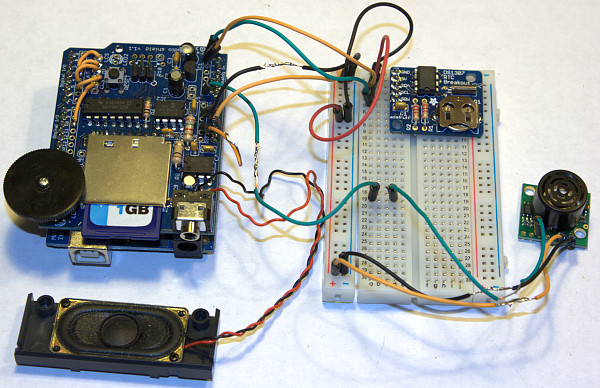
In “How to Build an Arduino Pest Repeller on Linux” the MaxBotix is soldered to the WAVE shield. For this project we’re using a solderless breadboard to connect the components. Solderless breadboards are wonderful for fast prototying and experimentation. The WAVE shield sits on top of the Arduino, so you’ll connect your wiring to the WAVE shield rather than the Arduino. The power and analog pin markings aren’t very readable on the WAVE shield, so you might want to make a little diagram from the Arduino for reference. Figure 1 (above) shows how they go together, and I shall leave it as your homework to make yours prettier and more permanent.
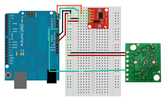
Figure 2 should make the connections a little clearer. The figure was created in the Fritzing printed circuit board (PCB) prototyping program. Fritzing didn’t have a ready-made image for the MaxBotix, so I hacked one in GIMP. (The MaxBotix is not to scale.)

If the diagram isn’t clear enough, make your connections like this:
- The DS1307 has a five-pin header. Connect this to column E, rows 1-5 on the breadboard. NOTE: the order of the pinouts varies on these little RTCs, so make sure you’re connecting to the right ones.
- Connect A5 on the WAVE shield to the row corresponding to the DS1307 SCL pin.
- Connect A4 on the WAVE to the row corresponding to the DS1307 SDA pin.
- Connect one GND pin on the WAVE to any pin in the ground rail on the breadboard.
- Connect the WAVE 5V pin to any pin in the power rail on the breadboard.
- Connect one ground pin on the breadboard to the row corresponding to the DS1307 gnd.
- Connect one power pin on the breadboard to the row corresponding to DS1307 5V.
- Connect GND and +5 on the MaxBotix to the ground and power rails.
- Connect AN on the MaxBotix to any empty row on the breadboard.
- Connect A0 on the WAVE shield to the same row.
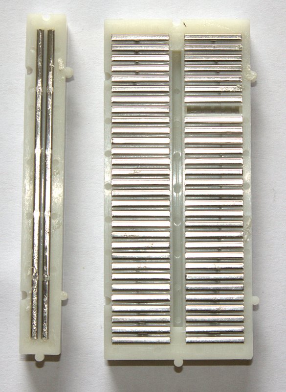
If you’re not familiar with solderless breadboards, think columns and rows. The columns are the common power and ground rails, and the rows are for power and signals. Figure 3 shows the backside of a breadboard with the sticky backing removed, exposing the metal rails. These rails are made of conductive metal and have tie pins for securely holding your jumper wires.

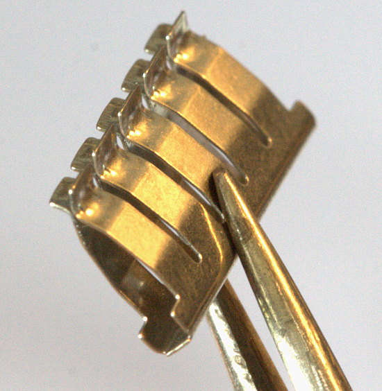
On my little breadboard, each row has five tie pins (figure 4).
Multiple Power Draws from the 5V Pin
You can run multiple devices off the Arduino’s 5V power pin as long as the total current draw is not excessive, and you use a common ground. So how much power draw is too much? There isn’t a precise answer, but we can calculate a workable estimate.
There is an onboard voltage regulator that will shut the board down when the current draw or temperature is too high. The maximum draw for each I/O (input/output) pin is 40 milliamps (mA), and in real life you don’t want to push it that hard, so say 20 mA for a safe margin. An Arduino board draws maybe 40 mA at idle. The USB plug is protected by a soft fuse that opens at 500 mA, and resets when the excessive demand stops. To make a long story short, use a total draw of 300 mA (the total of everything plugged into the board, and onboard) as a ballpark working limit. The Maxbotix draws around 3 mA at 5 volts (V), and the DS1307’s power demand is measured in nano-amps (nA). The WAVE shield uses about 100mA when it’s playing audio files. So for this project we’re well within conservative limits.
The Arduino can draw power from the USB port, a battery pack, or a switching power supply with a 2.1 millimeter (mm) center-positive plug. The safe power supply limits are 7-12 V.
Testing the Real-time Clock
Let’s load a sketch to test the DS1307 RTC. You’ll need the RTC and Wire libraries. Wire should be included in Arduino core, which you can confirm by looking in/usr/share/arduino/libraries/, and in your Arduino IDE you should have File > Examples > Wire.
 There are several RTC libraries. I’m using the the Adafruit RTClib. After you download and install this, take note of the
 keywords.txt files for both the Wire and RTC libraries, because these list all the datatypes and functions, which I think is a lovely thing to do. It surely beats trolling the code to find them.
#include <wire.h>
#include "RTClib.h"
RTC_DS1307 RTC;
void setup () {
    Serial.begin(9600);
    Serial.print("nThe current date and time will be updated every three seconds:nn");
    Wire.begin();
    RTC.begin();
}
void loop() {
    DateTime now = RTC.now();
    Serial.print("The day of the week is ");
    Serial.print(now.dayOfWeek(), DEC);
    Serial.println();
    Serial.println("The date and time are:");
    Serial.print(now.year(), DEC);
    Serial.print('/');
    Serial.print(now.month(), DEC);
    Serial.print('/');
    Serial.print(now.day(), DEC);
    Serial.print(' ');
    Serial.print(now.hour(), DEC);
    Serial.print(':');
    Serial.print(now.minute(), DEC);
    Serial.print(':');
    Serial.println(now.second(), DEC);
    delay(3000);
    if (now.dayOfWeek() == 3) {
    Serial.print("nhello, we have a match.nn");
    }
    else {
      Serial.print("nI am ever so sorry, your numbers don't match. n");
    }
}
When the day of the week in your if statement matches the day of the week as reported by your DS1307 RTC, you will see something like this:
The current date and time will be updated every three seconds:
The day of the week is 3
The date and time are:
2014/5/21 15:1:37
hello, we have a match.
Hurrah, we triggered an event based on a particular day! Now change the number in the if statement to see what a not-match looks like:
The current date and time will be updated every three seconds:
The day of the week is 3
The date and time are:
2014/5/21 15:2:43
I am ever so sorry, your numbers don't match.
Take special note of the Serial.print and if statement syntax, because we’re calling the various time functions directly, rather than using variables. The time and date functions are demonstrated in the example RTClib sketches, and are listed in the keywords.txt file. The dayOfWeek() function numbers the days of the week from 1-7, starting on Monday, so 3 is Wednesday. (One way to learn these things, absent coherent and thorough documentation, is to read the source code, in this case RTClib.cpp. Another way is trial and error.)
This example shows how to match multiple conditions. To trigger an event, such as playing a reminder message, the sensor must detect movement at 3:45PM:
if ((a0value < = 40) && (now.hour() == 15) && (now.minute() == 45))
See it all put together in our complete sketch in part 2.
References
Ladyada.net Arduino Tutorials
Arduino language reference
An excellent introductory book for novices is Programming Arduino: Getting Started with Sketches by Simon Monk, and Arduino Cookbook, 2nd Edition by Michael Margolis is great if you already know a little about electronics and a smidgen of C programming.


