A previous article covered what is involved in construction and initial use of the Open Source Ormerod 3D Printer on Linux. This time around we’ll take a look at how to design custom objects by creating the right files to send to your 3D printer, all using Free and Open Source Software.
Like many 3d printers, the RepRapPro Ormerod expects a g-code file to be sent to it telling it how to go about printing something. A g-code file contains a series of commands that move the print head location, extrude or retract the plastic, set the temperature of the hotbed and the hotend that melts the plastic, and various other commands. If you have the gcode file for an object you previously printed and have the same printer in a similar working order then you should be able to make another, identical, print of the same object.
A very common file format for 3d printed objects is STL files. An STL file describes an object that can be printed but it does not include some details that relate to a specific printer or specifications that can be customized depending on how much time and plastic you want to invest in a print. Things that change from printer to printer include how fast you want your printer head to move and how quickly you can extrude much plastic from your print head.
For any print job you might like to vary the how much plastic is used on the internal area of an object. For example, when prototyping you might like a less rigid object that prints in 20 percent of the time. Once you have perfected the design you can use more plastic (and time) during the print to obtain a more robust result.
You can create an STL file using OpenSCAD and then use the Slic3r program to convert an STL file into a g-code file for your printer. I’ll take you through this process, below.
OpenSCAD
While it is possible to hand write both g-code files and STL files, you probably want to work at a higher level again. OpenSCAD uses a text file to let you build up a 3D object by addition and subtraction of primitive shapes. For example, a motor mount might start with a rectangle and have a hollow cylinder for the shaft and three M3 bolt holes which are 120 degrees apart and 45mm from the center of the shaft. If you have offsets, angles, and measurements like this then OpenSCAD might be the fastest way to design your object for printing.
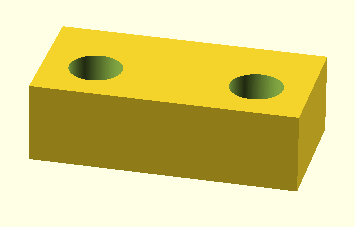
An example scad file is shown below. As you can see, there are one cube object and two cylinders in the SCAD file. The outermost difference() directive tells openscad that each object after the cube should be removed from the material that the cube has placed down. So in this case the cylinders each drill a hole in the cube. Perfect for creating a means to mount this new object to an existing one. Note that difference() can work on any arbitrary objects, not just cubes and cylinders. You can also create a union of many objects to build something up bit by bit or just leave the intersection of many objects. The two translate commands move the drawing point for anything in their scope. So in this case the first cylinder will be moved to 2,2 and the second to 8,2 relative to where the cube was started from.
module thing()
{
  difference() {
    cube( [ 10, 5, 3 ] );
    translate([2,2,-1]) {
      cylinder(7, r=1, $fn=200);
    }
    translate([8,2,-1]) {
      cylinder(7, r=1, $fn=200);
    }
  }
}
thing();You may notice that the translate commands each include a z-axis movement to -1 and that the cylinders are drawn much larger in the z-axis than the cube was (7 units instead of 3). This way the hole made by the cylinder will go all the way through the cube and OpenSCAD will not try to leave a fine or zero height portion of the cube skin at either end. It can be convenient to model the object using union() instead of difference() and use the drawing of the larger z-axis to see where the holes will be placed in your final object. Once you are happy that the holes are in the right place switch over the difference mode to have them subtracted from the render rather than added.

The translate command used above comes from a list of Transformations that are available in OpenSCAD, including rotation, scaling and mirroring. These can be arbitrarily nested. For example, you might want to create a mounting plate that includes one part at 90 degrees to a base plane. This arrangement might be needed to mount a motor to a robot shell or a light to the end of a pipe. If you are making a mounting then you will want bolt holes in both planes of the object, so inside the rotate()ed part you will then want to translate to the right location to drill out the mounting holes. 3d printing is very convenient for making an object that you can use to cleanly attach two existing objects.
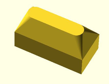
A transformation in OpenSCAD that might be useful is the convex hull(). I think about the Convex Hull different from scaling, rotation and translation. Loosely speaking it takes a collection of objects and creates a superset object that is like placing wrapping paper around the objects with the paper stretched to its maximum. For example, changing the difference() to hull() in the above will produce a result like the one shown below. The two cylinders extend beyond the cube, and you can see half of the end of each cylinder at the extremes of the very top of the object. However, from there you see a smooth amount of material going to the corners of the cube to create a single piece filled object.
OpenSCAD has two render modes; ‘Compile’ (F5) and ‘Compile and Render’ (F6). The former can be considerably faster than the later but the render option is much closer to what the final product will look like. To create an STL file using OpenSCAD use File/Export/Export as STL. You must have performed a render before you can export. The information section in the bottom right will mention this if it is needed, though you might not notice that at first.
Slic3r
Now that you have created an STL file using OpenSCAD you can use Slic3r to produce g-code for your printer. You might notice that Slic3r allows you to specify STL files on the command line, and if you run slic3r object.stl you will see a new object.gcode file. Though you might want to avoid printing that particular g-code file. This is because Slic3r may not use any profiles that you have set when executed this way. Instead it might generate the g-code files using default or other settings.
Using the below bash aliases I setup my Slic3r to use my default settings and also added a command to generate objects using more plastic for a final print run. The profile files for an Ormerod 1 printer and Ormerod 2 are up on github.
alias slic3r=”/usr/bin/slic3r
–load ~/.Slic3r/filament/Ormerod-0.5.ini
–load ~/.Slic3r/print/Ormerod-0.5.ini
–load ~/.Slic3r/printer/Ormerod-0.5.ini “
alias slic3r-heavy=”/usr/bin/slic3r
–load ~/.Slic3r/filament/Ormerod-0.5.ini
–load ~/.Slic3r/printer/Ormerod-0.5.ini
–load ~/.Slic3r/print/Ormerod-0.5-heavy.ini “
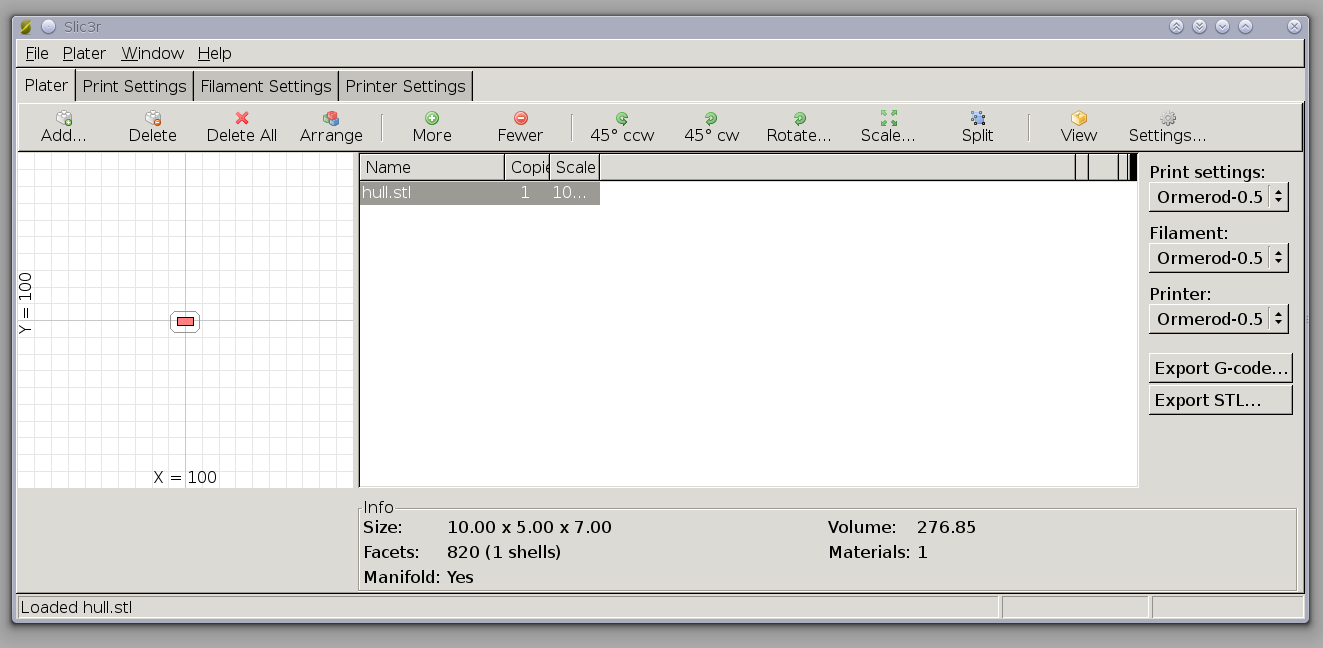
Shown below is the main Slic3r window. You can load one or more STL files to print. Clicking on More lets you place many identical copies of the same object on the print plate shown on the left. This can be useful if you have an STL file that you are happy with, but require 40 of the objects to be printed. If they are small enough you can run 5×4 of them on a single print run so you don’t have to keep clearing away a single object and restarting the print run.
You can also rotate, scale, and position where on the print bed the object(s) that you are printing will appear. Moving the object can be handy if you don’t want to wear out the tape on the print surface at a specific location or you find that the print head operates in a more stable way at a certain location, for example with the print head closer to the z-axis on an Ormerod.

One drawback that I encountered using Slic3r was when the STL file was in the wrong orientation to print. While you can rotate the object in Slic3r from the toolbar you don’t get to specify which axis to rotate around. A specific example of this was a stand for a tablet that I found on Thingiverse. This stand had a curved back and the default orientation of the STL file had that curved part being printed first. It was going to be much more successful to print the stand in the orientation that it would be used in so that the curved part was not trying to support the whole stand. This lead me to use Blender to load, rotate, and reexport the STL file for Slic3r to see in my desired orientation.
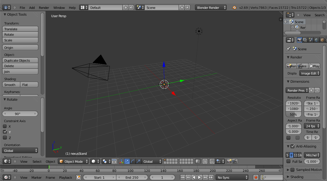
Using Blender can be a little daunting at first. Object selection happens with the right mouse button by default, and there are many thing that make sense in the environment but which might not be intuitive to somebody not familiar with 3d modelling. The following steps will let you import an STL file, rotate it, and save the updated object as a new STL file:
-
Start up Blender
-
Press Delete to remove the default cube, confirm this.
-
Use the menu File/Import/STL and select the original file with the orientation you wish to correct.
-
In the object tools on the left side click the rotate button, toward the bottom of that vertical panel you should see rotation options. If these options do not appear you might have to click the rotate button a second time. Click the x or y axis and in the Angle input enter 90 and press return to perform it.
-
Use File/Export/STL to save the rotated object to a new STL file.
-
Use Slic3r on the new object file to prepare it for printing as with any object you want to print.

Unfortunately the full usage of Blender is well beyond the scope of this article. It is certainly a very powerful modelling package, though some of the techniques take a while to pick up. Much of the animation and advanced rendering available in Blender doesn’t make sense for 3d printing. But Blender is extremely capable at letting you design objects which will export to STL and can then be 3d printed.
Final Thoughts
OpenSCAD makes creating uniform objects fairly simple, for example, mounting plates, attachments for servo motors, little robots etc. Creating more organic looking objects might be simpler in a 3d modeling package such as Blender. Being able to use Slic3r from the command line with a desired profile helps in making quicker, less plastic-heavy prototype prints. The same STL file can then be fed into a more time and plastic-heavy profile in Slic3r to create a more durable final print if desired.
We would like to thank RS Components for supplying the RepRapPro Ormerod used in these articles. The RepRapPro Omerod and RepRapPro Omerod 2 printers are available for purchase on RS Components’ Australian website while stocks last, or through RS Components’ main website, if you’re ordering internationally.


