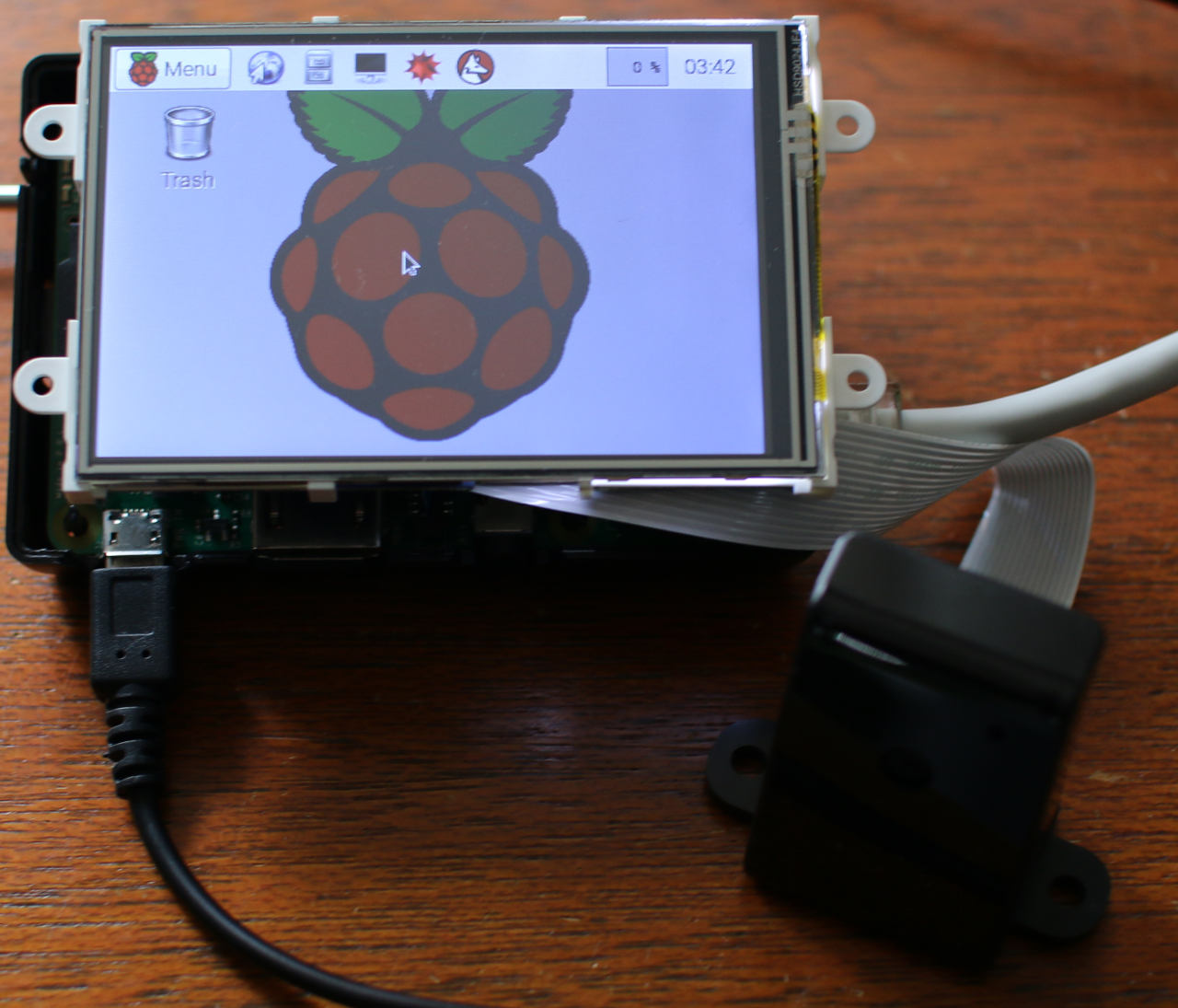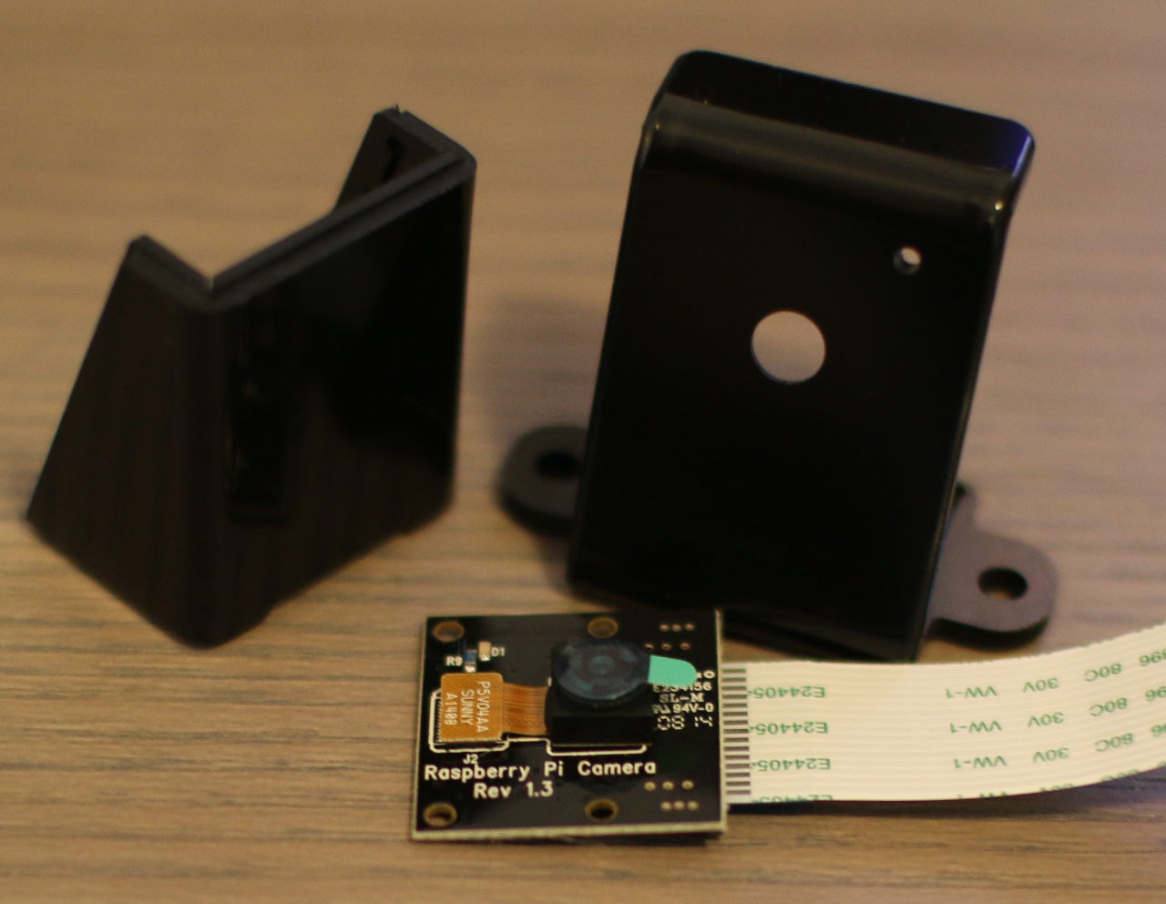
The Raspberry Pi and Pi2 are economical little ARM machines which can happily run Linux. The popularity of the Raspberry Pi and compatible Pi 2 models means that a great deal of accessories are available. These accessories include the PiNoir Camera and 4D Systems’ touch-sensitive, 3.5-inch display.
The PiNoir camera is so named because it does not have an Infrared Filter (no-IR). Without an IR filter the camera can be used at night, provided you have an infrared light source. With night vision you can use the Raspberry Pi as an around-the-clock surveillance camera monitor, baby monitor, or to give vision to a robot. The PiNoir Camera comes without a case, so you might like to pick up something to help protect it.
I’ll be setting up the 4D Systems screen and then taking a look not only at the PiNoir Camera, but how well it functions in combination with an infrared light source which offers a fairly wide beam and up to 10 meters of lighting. The camera connects to the camera Serial Interface (CSI) port on the Raspberry Pi and the screen connects to the 40 pin expansion header on the Raspberry Pi.
The 4D Systems 3.5-Inch Screen
The 4D Systems screen runs at a 480×320 QVGA resolution with 65k colors. Physically the screen is about the same size as the Raspberry Pi 2. The screen mounting screw tabs extend a little beyond the Raspberry Pi on the USB connector side of the device.
The datasheet for the screen mentions that you should include some shielding to prevent accidental electrical contact between items on the back of the screen and the Raspberry Pi. I found that the socket that connects the screen and USB ports provide a decent support for the screen. One chip could be easily made to touch the Ethernet connector on the Raspberry Pi, so some form of non-conducting standoff would probably be advisable to stop that from happening. There are also male pins on the back of the screen, though they seem to have a reasonable clearance from the Raspberry Pi, though again perhaps some form of shielding would be wise. The best solution would be to create a case with mounting holes for both the Raspberry Pi and screen which would keep both at the correct distance from each other.
There are drivers for both the Raspberry Pi and Pi2 models for Raspian which include screen and touch support. The Raspberry Pi 2 has a 40 pin expansion header running down one side of it. The back of the screen has a 26 pin female header to connect to the Raspberry Pi. The first 26 pins on the Raspberry Pi2 header are in the same configuration as the earlier Pi models. The common 26 pins are at the end farthest away from the USB sockets on the Raspberry Pi 2.
Before connecting the screen you should install the drivers for it. These are linked from the download section of the manufacturer 4D Systems’ product page. I was running Raspbian 7 (Wheezy) and used the drivers from kernel4dpi_1.3-3_pi2.deb to test the screen. Setting up the screen drivers is done by installing the kernel package as shown below. I found that if I performed an apt-get upgrade then I had to also reinstall the kernel4dpi to get the screen working again.
root@pi:~# wget https://.../kernel4dpi_1.3-3_pi2.deb
root@pi:~# dpkg -i kernel4dpi_1.3-3_pi2.deb
...
Enable boot to GUI [Yn]y
After powering down the Raspberry Pi and attaching the screen I could see the boot messages as I restarted the Raspberry Pi but unfortunately, once booting was complete I saw the screen backlight but no image. I was then running kernel version Linux pi 3.18.9-v7+. After digging around, I noticed in /etc/rc.local the following line which should have brought up an X session on a framebuffer device which is backed by the screen.
sudo -u pi FRAMEBUFFER=/dev/fb1 startx &
From an SSH session I decided to run startx with the selected FRAMEBUFFER and the screen came to life with a nice desktop. My installation of Raspbian had S05kdm in its default runlevel (2) startup. Disabling S05kdm and rebooting brought up a graphical session right after boot as one would hope.
The screen provides a framebuffer device which is quite handy, as it allows you to view text, images, and video without using a full desktop if that is what you want. The following commands will view an image or video directly on the screen. Toolkits such as Qt will also let you run on a framebuffer.
root@pi:/usr/share/pixmaps# fbi -T 2 -d /dev/fb1 MagicLinuxPenguins.png
root@pi:~# mplayer -vo fbdev:/dev/fb1  -vf scale=480:320  test.mkv
Touch calibration happens at two levels: using ts_calibrate on the framebuffer and xinput_calibrator for the X Window session. Calibration in both cases is fairly simple, clicking on four or five positions on the screen when asked. The screen orientation can be changed allowing four different rotations using the /boot/cmdline.txt file. All of these procedures are well documented in the datasheet for the screen.
Dimming and turning off the backlight can apparently be controlled using GPIO18 and an exposed /sys/class/backlight/4dpi/brightness file. Although I had a jumper on the J1 connector of the screen in the PWM position, writing to the brightness file did not change the screen brightness while running an X session. Perhaps X itself was in charge of the screen dimming or I had a configuration issue with the Raspberry Pi 2.
The PiNoir Camera
 The PiNoir Camera is capable of capturing 30 frames per second for 1080p video and still images up to 5 megapixels, which is 2592×1944. The camera comes connected to a board with a fairly short ribbon cable attached which you then attach to the Raspberry Pi. The Raspberry Pi has a CSI port near the Ethernet port to connect the camera ribbon cable into. There is a clip which you pull upwards on each end and then you can move the clip backwards a little bit allowing the ribbon to be inserted into the CSI port. The clip can then be moved back and pushed down to lock the ribbon into place. The manuals mention that the camera and ribbon are static sensitive. After grounding myself before starting to assemble the camera into its enclosure and connecting the camera ribbon to the CSI port the camera worked fine.
Once the hardware is connected you might need to enable the CSI port in software. To do this run raspi-config and select Enable Camera from the menu. You will then have to reboot your Raspberry Pi.
The raspistill program will let you get your first still image from the camera. The only thing you’ll need to tell it is where to save that image file to, as shown below. A 5-second delay will precede the actual image capture and the result will be saved into test.jpg. I found that the light setup was better with this delay, using a –timeout 100 parameter to take the image after only a 100 millisecond delay resulted in an image with much poorer exposure.
pi@pi~$ raspistill  -o test.jpg
pi@pi~$ raspistill --timeout 100 -o badlight.jpg
To test how well exposed an image was after camera startup I took a time lapse series of 10 images, one each second using the below command. It took about 3 seconds for the image to go from a rather green image to a much more color-rich image.
pi@pi ~ $ raspistill --timeout 10000 --timelapse 1000
                     --nopreview -n -o test%04d.jpg
The raspivid tool is a good place to start when you want to get video from the camera. Unfortunately the test.h264 file created by the first command will be without any video file container, that is, just the raw h264 video stream. This makes it a bit harder to play back with normal video players, so the MP4Box command can be used to create an mp4 file which contains the raw test.h264 stream. The test.mp4 can be played using mplayer and other tools.
pi@pi ~ $ raspivid -t 5000 -o test.h264
  pi@pi ~ $
  pi@pi ~ $ sudo apt-get install -y gpac
  pi@pi ~ $ MP4Box -fps 30 -add test.h264 test.mp4
If you want to export the video stream over the network, gstreamer might be a more useful tool. There is a gst-rpicamsrc project which adds support for the Raspberry Pi Camera as as source to gstreamer. Unfortunately, at the time of writing gst-rpicamsrc is not packaged in the main Raspbian distribution. Installing the libgstreamer1.0-dev package allowed me to git pull from the gst-rpicamsrc repository and build and install that module just as the commands in its README describe. I’ve replicated the commands below for ease of use.
pi@pi ~/src $ sudo apt-get install libgstreamer1.0-dev  libgstreamer-plugins-base1.0-dev
pi@pi ~/src $ git clone https://github.com/thaytan/gst-rpicamsrc.gitpi@pi ~/src $ cd ./gst-rpicamsrc/
pi@pi ~/src $./autogen.sh --prefix=/usr --libdir=/usr/lib/arm-linux-gnueabihf/
pi@pi ~/src $ make
pi@pi ~/src $ sudo make install
Now that you have the gst-rpicamsrc module installed you can send the h264 stream over the network using the below commands. I found that even at 1080 resolution and a high profile there was very little CPU used on the Raspberry Pi2 to stream the camera. CPU usage was in the single-digit values in a top(1) display.
The Raspberry Pi supports encoding video in hardware and because the rpicamsrc is supplying h264 encoded video right from the source I suspect that the hardware encoding was being used to produce that video stream. The first two commands stream 720 or 1080 video with a slightly different encode profile. The final command should be run on the ‘mydesktop’ machine to catch the stream and view it in a window.
pi@pi~$ gst-launch-1.0 -v rpicamsrc bitrate=1000000
  ! video/x-h264,width=1280,height=720,framerate=15/1
  ! rtph264pay config-interval=1
  ! udpsink host=mydesktop port=5000
  pi@pi~$ gst-launch-1.0 -v rpicamsrc bitrate=1000000
  ! video/x-h264,width=1920,height=1080,framerate=15/1,profile=high
  ! rtph264pay config-interval=1
  ! udpsink host=mydesktop port=5000
  me@mydesktop ~$ gst-launch-1.0 udpsrc port=5000
  caps="application/x-rtp,media=(string)video,clock-rate=(int)90000,encoding-name=(string)H264"
  ! rtph264depay ! decodebin ! autovideosink
Night Vision with the PiNoir Camera and IR source
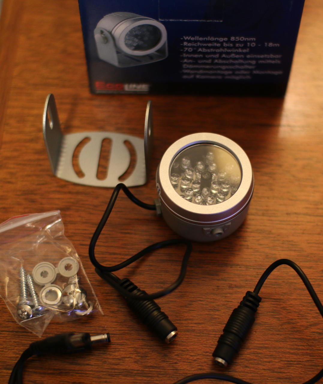
The datasheet for the PiNoir camera states that it wants infrared light at around 880nm wavelength. The TV6700 IR Illuminator operates at 850nm so might not be directly on the sweet spot that the PiNoir is expecting. The specifications of the IR illuminator are a 10 meter range and a 70 degree radiation angle. The LEDs are listed for up to 6,000 hours of use and there is an automatic on/off capability to turn off the illuminator during the day.
 The TV6700 IR illuminator comes with a smallish round metal cylinder, one end of which you can see LEDs through a clear cover. The unit wants a 12-Volt power supply and there is a Y splitter with one female and two male DC jacks. If your existing camera’s power supply is 12 V and has some spare power capacity then the splitter will let you grab power right off the camera and mount the IR illuminator nearby. There is also a U shape bracket and some mounting screws.
An initial test of the illuminator was done in a room about 5 by 5 yards big. At night with a 3-Watt LED desk light and a fairly dark LCD screen I could just make out items such as a fan in the near ground (2 feet from the camera) but items on a bookshelf 2 yards from the camera were much harder to see, only being able to read very large text on the spines of white books. Turning off the 3 W LED blackened the PiNoir camera display completely. It seems the light emitted by the monitor when viewing a dark image is not enough for the PiNoir Camera to provide much of an image by.
Leaving the 3 W normal LED light off and turning on the IR illuminator made the whole picture clearly visible in greyscale. Waving a hand in front of the camera came through in real time although the room was dark. Using IR lighting and a camera that does not filter IR has the advantage of being able to stream fast movement properly. Using a still camera to take a sequence of longer exposure images would likely result in a collection of motion blur images.
Moving to an outside setting with a large grass lawn at night I could make out a person a little over 7 meters away from the Raspberry Pi and almost over the entire range of width of the captured video image from the camera. Perhaps only getting 7 meters visibility was the result of not precisely matching the infrared wavelength that the PiNoir camera expects.
RPi for Video Monitoring Applications
While the Raspberry Pi runs perfectly well without any display, some applications might benefit from being able to display information on demand. Because the 4D Systems 3.5 inch screen is about the same dimensions as the Raspberry Pi board it can offer a display without increasing the physical size of the Raspberry Pi or requiring external power for the screen.
Being able to produce and stream 1080 h264 encoded video using the PiNoir camera and in low-light situations opens up the Raspberry Pi to video monitoring applications. For example, using a headless Raspberry Pi with a PiNoir camera as a baby monitor. The main downside to using the Raspberry Pi as a monitor is that the CSI cable is rather short, especially when compared to a USB cable. If you want a Raspberry Pi at the heart of your robot then you can stream nice robot eye camera vision over the network without a great impact on the robot’s CPU performance.
The IR source is a must have if you plan to use the PiNoir camera for security monitoring. Being able to see who is doing what while they might be unaware of the camera or (infrared) light source helps you respond to the situation in an appropriate manner.
We would like to thank RS Components for supplying the hardware used in these articles. The PiNoir Camera, 4D Systems touch-sensitive 3.5-inch display, infrared light source, and camera case are available for purchase on RS Components’ Australian website while stocks last, or through RS Components’ main website, if you’re ordering internationally.


