In this tutorial, we’ll learn how to control a robotic arm from the BeagleBone Black. Then we’ll give your project the ability to manipulate real world objects and perform repetitive tasks for you.
A robotic arm uses many servo motors to turn arm sections, wrists and move a gripper (fingers). The more servos used, the more moving joints the arm will have leading to greater flexibility. More servos also brings greater cost and control complexity.
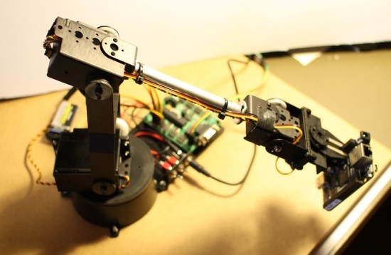
The base model of the Lynxmotion AL5D robot arm uses five servos; one for rotation, a shoulder joint, an elbow, a wrist and a gripper for holding things (sort of like the thumb coming together with all fingers).
The little computer board shown next to the robot arm in the picture above is the Serial Servo Controller (SSC-32). The SSC-32 accepts commands on a serial port and lets you control up to 32 servos.
We have already seen that the BeagleBone Black is capable of directly controlling servos so you might wonder why the SSC-32 might be useful. The main advantages of the SSC-32 are that it can handle speed-based servo movement and batch multiple servo movements together into a single logical action. For example, you can issue a single command to move the shoulder, elbow, wrist and fingers to a specific location in 2 seconds and each servo will move at a speed that will cause it to arrive at your destination at the same time as the other servos. With the SSC-32 you do not have to consume 5-6 of the pulse-width modulation (PWM) outputs on the BeagleBone Black to run the robot arm and the SSC-32 takes care of providing the servo motors the 6 Volts they need.
Assembling the robot arm
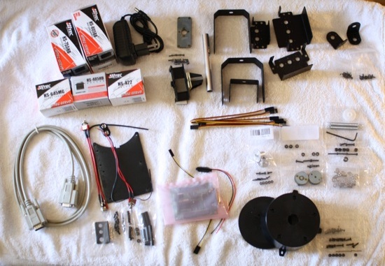
The robot arm comes in kit format and assembly instructions are available online. There is also a video showing the key points of the assembly process. I found slight differences between the above guides and followed the online instructions when in doubt. Basic assembly performed at a comfortable pace took me around six hours. You should definitely bolt the robot arm base to something, even if it is only a half meter square of MDF board. Otherwise you are likely to discover as I did that servo motors used by the robot arm can easily topple it over if the arm is not secured.
In the bottom left of the image is a RS-232 cable which can be connected to the DB-9 port of the SSC-32 for control. The SSC-32 is shown in an anti static bag in the middle of the lower part of the image. Right next to the RS-232 port on the SSC-32 are some TTL connectors which are of much greater interest for controlling the SSC-32 from the BeagleBone Black. TTL serial communication operates in a smaller voltage range and is simpler to work with from micro controllers than RS-232.
The two main U shape pieces between the shoulder and the elbow use friction plates to take some of the load off of the servos. There is also a spring that is fit between the servos to assist in bringing the arm back from extended maneuvers. The wrist can move up and down about 90 degrees. A wrist upgrade option is available to allow the wrist to rotate around its axis as well.
Attaching the Arm to the BeagleBone Black
The BeagleBone Black digital pins operate at 3.3 volts. A rather ominous warning message indicates not to use anything over 3.3 V on any pin of the BealgeBone Black. The SSC-32 operates at 5 V. Sending data from the BeagleBone Black to the SSC-32 will be fine as a 3.3 V “high” will still be detected as a “high” signal level on the SSC-32.
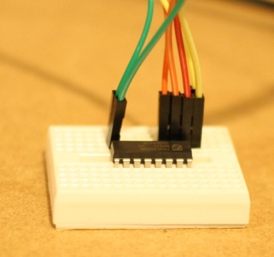
 Serial communication from the SSC-32 to the BeagleBone Black requires additional attention and some extra hardware to do voltage level shifting down to 3.3 V or lower to send to the BeagleBone Black. The 74HC4050 IC has support for level shifting six lines and input pins are over-voltage tolerant. So running the 74HC4050 at 3.3 V, one of the input pins can shift the 5 V serial signal from the SSC-32 to a 3.3 V signal that is within voltage range for the BeagleBone Black.
The BeagleBone Black has 4.5 universal asynchronous receiver/transmitters (UARTs). UART4 is toward the power and ground end of P9 making it convenient to connect wiring because you don’t have to count too far along any header. All of the pins of interest on the BeagleBone Black are on the outside of P9 starting with pin 1. The pins are ground (1), 3.3 V (3), skip over the next 3 pins, and then RX (11), and TX (13).
The 3 TTL serial pins of interest on the SSC-32 are right next to the DB9 connector and are ground, rx, and tx. These pins are clearly labeled with ground the nearer pin to the edge of the board.
The photograph of the 4050, above, shows a 3.3 V power line (red) going to pin 1 of the 4050. Pin 8 of the 4050 is ground and the green wires go to ground on the SSC-32 and ground (pin 1) on the BeagleBone Black.
The transmit line (pin 13) from the BeagleBone Black uses yellow cabling and can be connected directly to the receive RX pin on the SSC-32. These wires just meet on the breadboard for convenience, they do not connect to the 4050 at all. Level shifting has to be performed on signals bound for the receive RX (11) pin of the BeagleBone Black. I used orange wires for the signal going from the TX pin of the SSC-32 to the 4050 level shifter (pin 3 of the 4050). The level shifted signal is taken from the 4050 (pin 2, near power) and sent to the RX (11) pin on the BeagleBone Black.
Set up the BeagleBone Black
The Bonescript library includes support for serial IO. The upside to interacting with the serial port using the bonescript API is that the device tree overlays are set up for you automatically. Unfortunately I had some issues using that on the bone-debian-7.5-2014-05-14 image so could not test using the serialport API that ships with Bonescript.
A fall back which works well on revision C Debian-based and revision B Ångström Linux-based BeagleBone Black boards is to use the serialport node module instead. The downside of installing and using the node module is that you have to setup the UART device tree overlay yourself, either before running the program or using the startup files to setup the UART overlay.
The below commands will manually enable UART4 on the BeagleBone Black.
root@beaglebone:/lib/firmware# echo BB-UART4 > /sys/devices/bone_capemgr.*/slots
root@beaglebone:/lib/firmware# sleep 1
root@beaglebone:/lib/firmware# chown debian /dev/ttyO4
root@beaglebone:/lib/firmware# ls -l /dev/ttyO4
crw-rw---T 1 root dialout 248, 4 May 15 02:50 /dev/ttyO4
Then the serialport nodejs module can be installed for all users with the following command.
root@beaglebone:~# npm install -g serialport
For a quick sanity check that the wires are working as expected, the screen command can be used to query the version of the SSC-32 board as shown below. Note that on the screen the version information will overwrite the VER command when you press enter. It’s not pretty but it shows that bidirectional communication is happening.
screen /dev/ttyO4 115200
VER
SSC32-V2.03XE
For reference, I was using the bone-debian-7.5-2014-05-14-2gb.img image from and sdcard on a revision C BeagleBone Black for this article.
Moving the arm
If you connected the servo cables following the assembly instructions then servo 0 causes rotation in the base, servo 1 is the shoulder, servo 2 is the elbow, servo 3 is the wrist and servo 4 controls the gripper (finger and thumb).
The below code should move the gripper in and out once. First, the serial port for UART4 (/dev/ttyO4) is opened. Right after the open has happened the “ver” command is issued to the SSC-32 as a sanity check. After a few seconds the gripper will move one way and after a few more seconds it will move back in the other direction. In the commands written to move the gripper the ‘#4’ means we want to control servo 4 and the P1650 is what position to move the servo to. Each servo will have about 180 degrees of movement with one end at around 1000 and the other at 2000. I have chosen to move the gripper servo first to avoid any nasty surprises that sudden swift initial arm movement might present.
#!/usr/bin/node
var SerialPort = require("serialport").SerialPort;
var serialport = require("serialport");
var sp = new SerialPort("/dev/ttyO4", {
    baudrate: 115200,
    parser: serialport.parsers.readline("r")
 });
sp.on("open", function () {
    console.log('open');
    sp.on('data', function(data) {
        console.log('data received: ' + data);
    });
    sp.write("verr", function(err, results) {
        console.log('err ' + err);
        console.log('results ' + results);
    });

    setTimeout(function() {
        sp.write("#4 P1050r");
    }, 2000 );
    setTimeout(function() {
        sp.write("#4 P2050r");
    }, 4000 );
});
You can control all the servos in a single write command to get multiple servos moving at once in a group. The speed (S) command and time (T) options allow you to slow down the servo movement. The time command operates on all the movements in the group so that they will all move just as fast as needed in order to complete at the given time you supply.
Completing Movements In Order
In the above code there was a gap between the two movement commands. You can move a group of servos in one command which is terminated with the carriage return character. When you write another movement command then the Lynxmotion AL5D will immediately start on the new command. It is tedious having to keep track of how long a movement command will take in order not to step on its toes before it is complete.
The SSC-32 has a query command which will return a single character, a ‘+’ to indicate that the previous command is still in progress and a ‘.’ to indicate that the command is complete.
It might be useful to issue many movement commands in series to have the Lynxmotion arm complete a complex movement. This will require the ability to wait for the current movement to complete before sending the next movement command. In some programming environments this would be done using a sleep or delay function to do nothing for a period of time. In nodejs the normal convention is to pass a callback function that will be executed once an action completes. The below waitForIdle does this by polling the Lynxmotion arm with the query command and executing the callback when motion has completed.
The waitForIdle resets the complete flag and schedules the waitForIdle_func to execute shortly after. Inside waitForIdle_func() if the SSC-32 has indicated that movement is complete then the callback function is executed, otherwise the current state of motion is queried again using the “q” command. A single ‘.’ reply from the SSC-32 indicates completion so the on(‘data’) callback is extended to communicate that to the waitForIdle_func function.
var waitForIdle_complete = 0;
var waitForIdle_func = function( cb ) {
    if( waitForIdle_complete ) {
        cb();
    } else {
        sp.write("qr", function( err ) {
        if( err !== undefined ) {
            console.log('ERR ' + err);
        }
        });
        setTimeout( function() { waitForIdle_func(cb); }, 200 );
    }
}
var waitForIdle = function( cb ) {
    waitForIdle_complete = 0;
    setTimeout( function() { waitForIdle_func(cb); }, 200 );
}
sp.on('data', function(data) {
    console.log('data received __' + data + '__');
    if( data == '.' ) {
        console.log('movement complete!');
        waitForIdle_complete = 1;
    }
});
Using an async.queue allows the commands and waits to be listed simply and the drain() callback is executed when all the motion commands in the queue are complete. In this case the nodejs script simply exits at the completion of all movement.
The pushAndWait function is added to the queue itself to allow just the servo movement command to be added and an implicit wait command is inserted. To see the difference that adding pushAndWait makes, see the last four push() method calls which are almost equivalent to the final two pushAndWait method calls, one is scheduled to complete (T1500) move quickly than the other.
var async = require("async");
...
var q = async.queue(function (task, callback) {
	console.log('queue: ' + task.name);
	if( task.cmd ) {
	    sp.write( task.cmd );
	    callback();
	} else {
	    waitForIdle( function() { callback(); } );
	}
}, 1 );
q.drain = function() {
	console.log('queue: all items have been processed');
	process.exit();
}
q.pushAndWait = function( name, cmd ) {
	this.push( { name: name, cmd: cmd });
	this.push( { name: 'wait',  wait: 1 } );
	}
q.push( { name: 'close', cmd: "#4 P1050 T2000 r" });
q.push( { name: 'wait',  wait: 1 } );
q.push( { name: 'open',  cmd: "#4 P1900 T2000 r" });
q.push( { name: 'wait',  wait: 1 } );
q.pushAndWait( "close", "#4 P1050 T1500 r" );
q.pushAndWait( "open",  "#4 P1900 T2000 r" );
The same queue technique is useful for using other serial control protocols from nodejs, especially when the controller replies to each command and will not accept another command until the previous one has completed.
Point and Click Movement
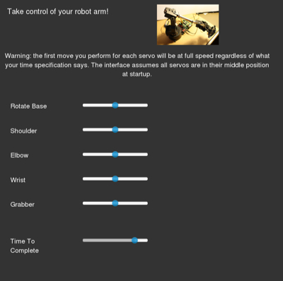
As with the 3-wheel robot base, the combination of Bootstrap, jQuery, and the bootstrap-slider projects allow a web interface to be quickly created. The web page consists of six sliders, five to control the servo positions and one to set the amount of time that the current movement should take. This last slider is very important as it allows larger movements to be performed at lower speeds in order to achieve smooth movement and to not put additional stress on the robot arm.
The entire server is less than 50 lines of code as seen below. As the servo sliders range from 0 to 100 the moveServo() function converts that value into a PWM setting (around 1000 to 2000) that the SSC-32 is expecting.
var b = require('bonescript');
var SerialPort = require("serialport").SerialPort;
var serialport = require("serialport");
var io = require('socket.io').listen(8888);
var ssc32 = new SerialPort("/dev/ttyO4", {
    baudrate: 115200
});
io.sockets.on('connection', function (socket) {
    console.log("have connection");
    var timeToCompleteMove = 1500;
    var moveServo = function( servonum, perc ) {
	if( typeof perc === 'undefined')
	    return;
	var servoval = 1000 + 1000 * perc/100;
	ssc32.write("#" + servonum + " P" + servoval + " T" + timeToCompleteMove + " r");
    }
    socket.on('base', function (v) {
	moveServo( 0, v.value );
    });
    socket.on('shoulder', function (v) {
	moveServo( 1, v.value );
    });
    socket.on('elbow', function (v) {
	moveServo( 2, v.value );
    });
    socket.on('wrist', function (v) {
	moveServo( 3, v.value );
    });
    socket.on('grabber', function (v) {
	moveServo( 4, v.value );
    });
    socket.on('time', function (v) {
	if( typeof v.value === 'undefined')
	    return;
	timeToCompleteMove = v.value;
    });
});
Other than the page styling the index.html includes many fragments like the following which creates a slider and sends a message to the server whenever the value of the slider is changed.
<div class="row">
  <div class="col-md-1"><p class="lead">Grabber</p></div>
  <div class="col-md-8"><input id="grabber" data-slider-id='grabberSlider'
           type="text" data-slider-min="0" data-slider-max="100" data-slider-step="1"
           data-slider-value="50"/></div>
</div>
...
$('#grabber').slider({});
$("#grabber").on('slide', function(slideEvt) {
    socket.emit('grabber', {
        value: slideEvt.value[0],
        '/end': 'of-message'
    });
});
Assuming that the code for controlling the robot arm is in /home/debian/bonescript/webinterface and that the main nodejs server is called lynxmotion-arm-server.js the below commands first make the Web interface available through the Cloud9 Web server that is already running on the BeagleBone Black and then arrange for the nodejs server to be started automatically.
cd /var/lib/cloud9
ln -s /home/debian/bonescript/webinterface arm
cd ./autorun
ln -s /home/debian/bonescript/webinterface/lynxmotion-arm-server.js .
This should allow you to control the arm with a web browser by visiting the URL http://bbb.ip.addr/arm/. The full source code for this is up on github.

We would like to thank RobotShop for supplying the robot arm used in this article.


