
A Computer Numerical Control (CNC) machine interprets a series of commands and creates a physical object for you. The object can be as simple as a few holes in a panel for lights or as complex as a large engine. At the simpler end of the spectrum, you might like to create a control panel with buttons at set distances from each other, or perhaps you also want a square hole for a display. Instead of measuring this out and using a drill press, you can attach your control panel to the cutting area of a CNC and have the machine create it for you.
CNC Machines
Hobby CNC machines look a bit like 3D printers, with the ability to move in at least X, Y, and Z dimensions, but instead of extruding plastic to create things, they have many cutting bits that let you slice away material to expose the final object you want.
A CNC can remove just a small amount of material, create holes right through something, or use a cutting head to engrave something on a panel. This is a big advantage if you want to create some button holes in a panel. The CNC can also engrave what the button does right next to the hole that it has created.
You control a CNC machine using a G-code file, which has commands that tell the machine where to move the cutting head. It also controls whether the head should be turned on and off and other things. A G-code file might tell the machine to move to an X=100 and Y=0 position from the current location, while not “cutting.” The CNC might interpret that command by accelerating the cutting head up to a maximum speed and then decelerating as it gets closer to the destination. The cutting distinction is useful because the CNC can move faster if it knows it is not meant to be cutting anything when moving the position of the cutter.
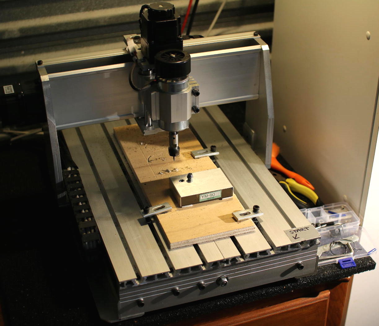
Hobby CNC machines are available for around a thousand dollars or less. Options range from the Shapeoko kit and X-Carve through to the “3040 CNC” machines from China (Figure 1), which can be found on eBay. The 3040 number indicates the size of the bed that might be serviced by the cutting tool (30×40 cm), although you are likely to get slightly less than that in each dimension.
The Smoothieboard has an Ethernet port and a 100Mhz microcontroller to read your G-code and tell the stepper motors on the CNC machine where to move to cut out your design. Using the Smoothieboard, you do not have to bring a PC close to the CNC to use it, and you can interact with the Smoothieboard from any machine over the network. Because the Smoothieboard is also open hardware, you can find many suppliers of compatible boards depending on your needs.
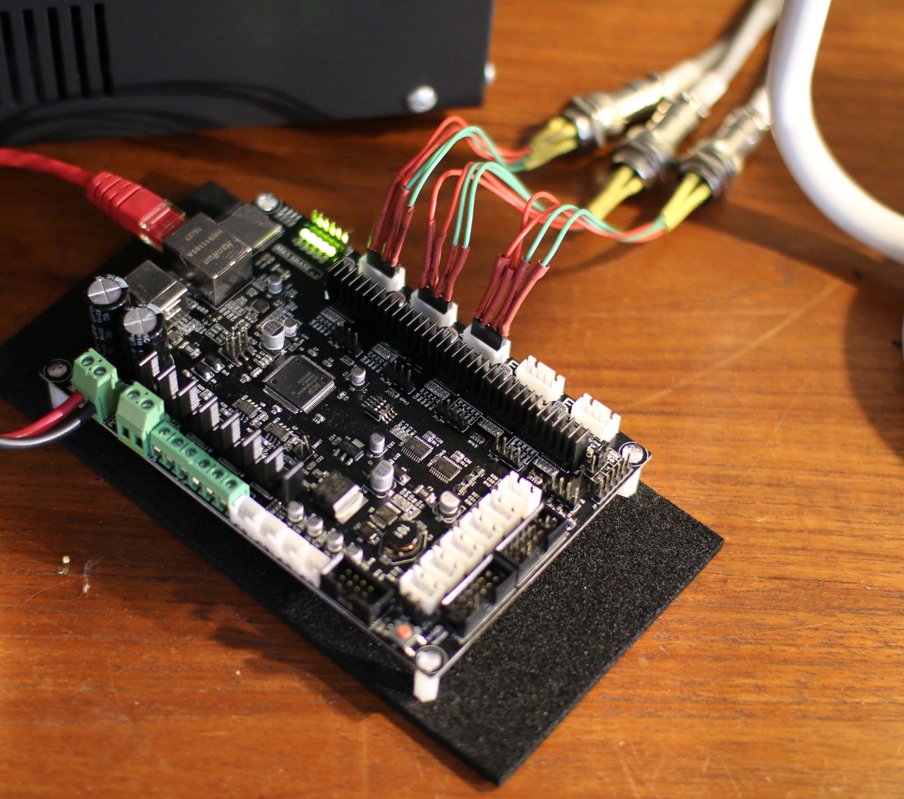
Figure 2 shows a Smoothieboard compatible board. The three stepper motors are connected to the X, Y, and Z connectors along the top of the board. The Ethernet cable is on the top left, and the DC power is connected to the left side of the board. The cutting spindle is on the left under the control of the original board and power supply.
The First Cut
It can be a little intimidating working out how to create G-code files and the process to start creating things with a CNC. A good place to start is with engraving and 2.5D milling. An introductory approach to doing 2.5D is to cut out a 2D pattern and then home the X, Y, Z to have the Z axis 0.1mm lower and recut the same design. This way you can move through 1mm thick material in multiple passes and keep a close eye on things as you go through the process the first time.
An example workflow for 2.5D milling starts with using Inkscape to lay out where you want to make your cuts. The first thing I normally do is open the “File/Document Properties” dialog and set the units to mm and the page size to the approximate size of the area I intend to cut. This helps to avoid surprises later, such as running over the edge of your material. A circle drawn in Inkscape can be used to create a hole in your material.
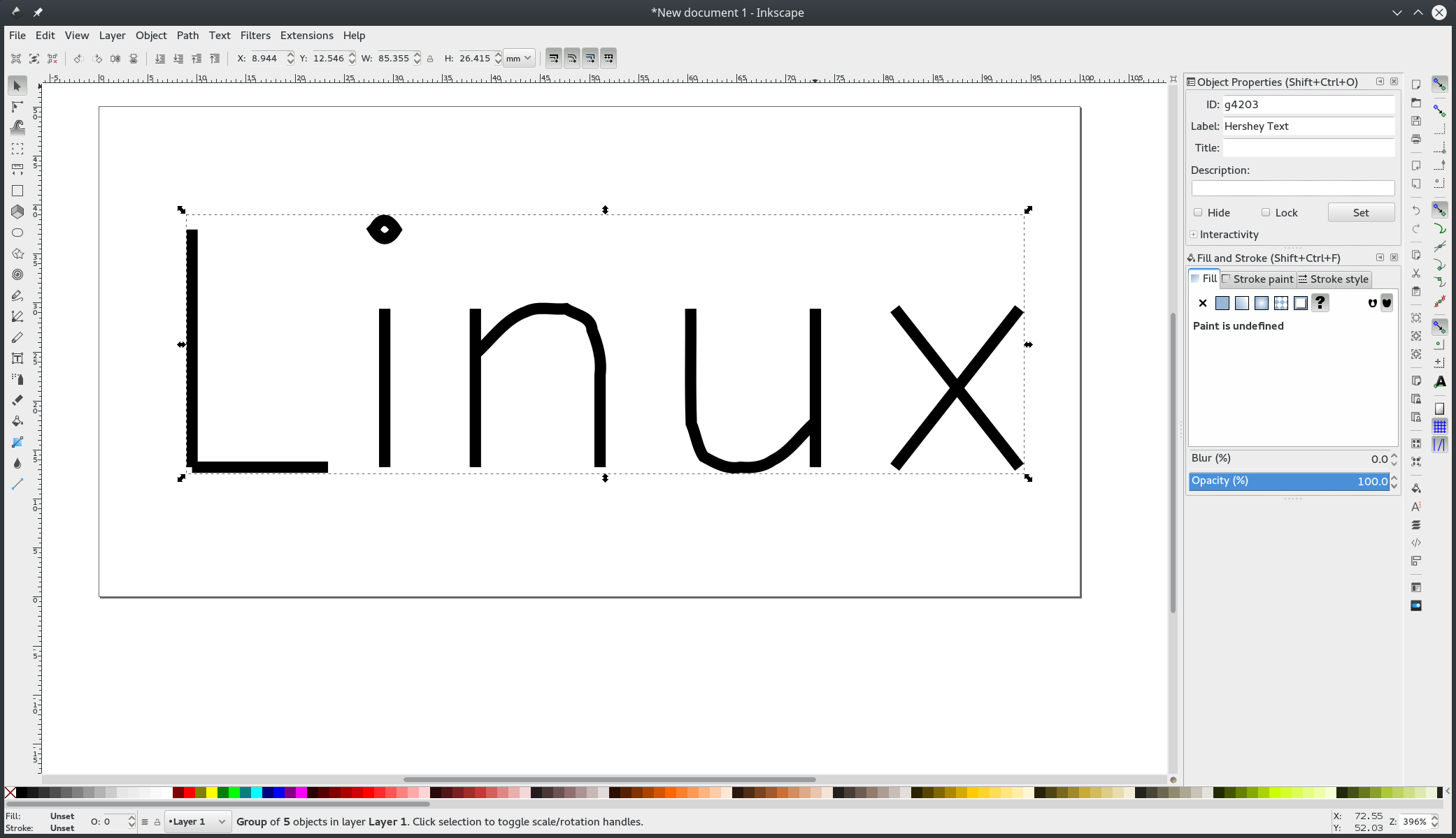
If you want to engrave some text, you might like to consider using the Hershey Text Inkscape plugin (Figure 3). The advantage of Hershey Text is that it is designed to be created on physical objects using a small number of passes of the cutting tool. If you are using an OpenType font by placing a normal text object in Inkscape, the cutting tool might have to perform many passes to remove all the material before you get something resembling what is on screen.
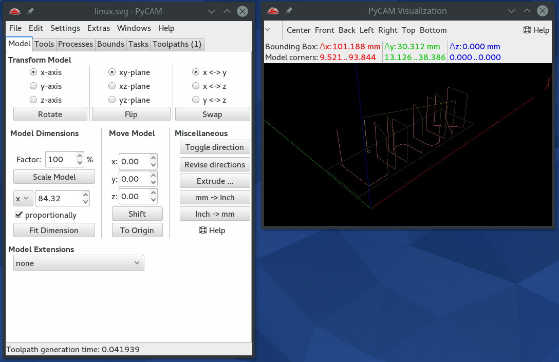
Once you have a design in Inkscape that you want to test, you can save that as an svg file and open it in PyCAM to generate your G-code (Figure 4). Once PyCAM is open, you should check a few things in the “Settings/Preferences” window. Make sure the General/Unit is set to the same measuring units you are using — mm in this case. In the G-code tab, there is the Safety Height setting, which is how far PyCAM will move the cutting bit upward before moving to another area. This setting helps you set enough clearance to avoid accidentally hitting the bolts that hold your material on the cutting tray. If there’s nothing to avoid, you can make the Safety height smaller.
Now that you have a G-code file, you need to upload it to the CNC machine and start a cutting job using that file. The Smoothieboard firmware should present an interface that resembles the pronterface tool used for 3D printing. There will also be a space allowing you to upload your firmware to the SD card of the CNC machine.
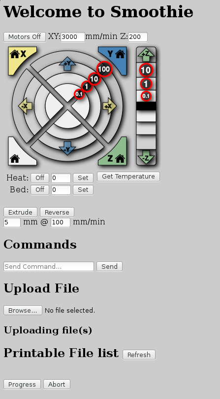
Before using the file you uploaded to engrave, it is very useful to have an idea of where the engraving is going to happen. You can adjust the location of the cutting head to one corner of the “page” that you used in Inkscape using the X, Y, and Z movement controls of the Smoothieboard web interface (Figure 5).
The telnet interface to the Smoothieboard can also execute G-code directly and has a collection of commands to allow you to look around the SD card and start or abort a CNC job. The below “G92” G-code command will set the X, Y, and Z home position to the current location of the cutting head. If you set the Z height to well above your material, you can tell Smoothieboard that that is the “top” of the material by telling it that it is at Z0. In the example, I have set the home position and then used “ls” to see the location of linux.ngc and “play” to start running that G-code file.
 > G92 X0 Y0 Z0

 > ls sd
 linux.ngc
 > play sd/linux.ngc
If cutting through the air looked good, you can lower the cutting head close to the material you are planning to cut and run the G92 command again. If you don’t want to cut into the corner of the material, you can set Z0.2 to tell the Smoothieboard that you are currently slightly above the Z home height. Then, when playing back the sd/linux.ngc file, the Smoothieboard will know that Z=0 is 0.2mm lower and should start at that lower height for the CNC job. It might take a few attempts to get the cutting head at just the right height to make some slicing into your material. It’s always best to cut too high a few times rather than cutting too low and potentially breaking the piece.
Final Words
The availability of fairly affordable CNC machines and replacement controller boards with fast microcontrollers and network connectivity makes it a great time to get into CNC. Many options are available including basing your CNC on a 3040 from China or using open source software and open hardware to run the show, perhaps starting out with with a Shapeoko. Depending on the material you are planning to cut, you might also have to retrofit a water-cooled spindle and some method to deliver cutting fluid to the cutting area.
I hope to cover more advanced CNC techniques in a future article — moving from 2.5D to full 3D CNC and 4D CNC, where you can also rotate the object you are cutting. Another great use for these machines is creation of custom PCBs. Prototyping speed is much greater without having to wait for slow shipping.


