
")
Start exploring Linux Networking and Administration by downloading the free sample chapter today. Download Now
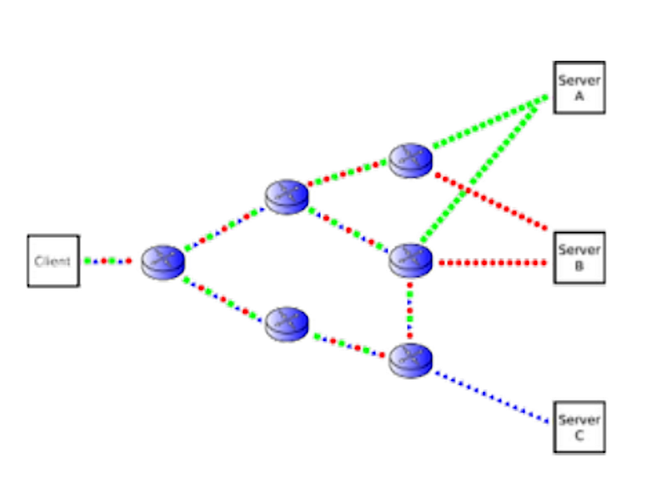
IP packets can only reach from end to end if they are routed properly. Network routers inspect packet headers, and make routing decisions based on the destination address.
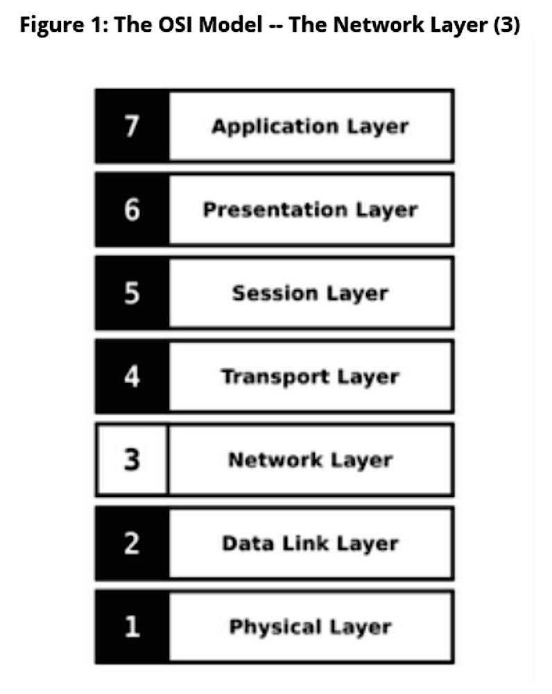
In this week’s LFCE sneak peek blog, we examine the OSI networking layers 3-1, which involve IP addressing, routing, and network hardware. Download the full sample chapter: Linux Networking Concepts and Review.
In part 1 of our Linux Foundation Certified Engineer Training Course sneak peek blog, we reviewed the OSI network layers 7-4. These are the layers that involve application protocols, session data management, and transport protocols.
Today in part 2 we complete the OSI layers review with layers 3-1. These include routing and control protocols, Internet protocols, classed and classless IP addressing, subnetting, and the physical network hardware.
OSI Layer 3: Network Layer
-
IP: Internet Protocol.
-
OSPF: Open Shortest Path First.
-
IGRP: Interior Gateway Routing Protocol.
-
ICMP: Internet Control Message Protocol.
The Internet Protocol
Originally the datagram service for TCP, the Internet Protocol now transfers many different higher level protocols. The Internet Protocol has two main functions:
-
Addressing.
-
Fragmentation.
The addressing function examines the address on the incoming packet and decides if the datagram (packet) is for the local system or for another system. If the address indicates the datagram is for the local system, the headers are removed and the datagram is passed up to the next layer in the protocol stack. If the address indicates the datagram is for another machine, then it is passed to the next system in the direction of the final destination.
The fragmentation component will split and re-assemble the packets if the path to the next system uses a smaller transmission unit size. There are two major versions of IP:
-
IPv4.
-
IPv6.
For additional information, please see https://www.ietf.org/rfc/rfc791.txt.
IPv4
IPv4 was the first major Internet Protocol version:
-
It is the most used protocol on the Internet.
-
The 32bit address size allows for 4,294,967,296 possible addresses.
-
The address space was exhausted on January 31, 2011.
-
The last allocation of blocks was given out on February 3, 2011.
The IPv4 address space exhaustion has been a concern for some time. There are different solutions for mitigating the problem:
-
The move from Classed networks to CIDR.
-
The invention of NAT.
-
The move to IPv6.
IPv6
IPv6 is the successor to IPv4.
example.com – 2001:500:88:200::10
IPv6 has a 128-bit address size that allows for 3.4×1038 possible addresses. IPv6 was designed to deal with the exhaustion of IPv4 addresses and other IPv4 shortcomings:
-
Expanded addresses capabilities.
-
Header format simplification.
-
Improved support for extensions and options.
-
Flow labeling capabilities.
To learn more, please visit https://ietf.org/rfc/rfc2460.txt.
IP Address Parts
IP addresses have two parts:
-
The Network Part.
-
The Host Part.
They are distinguished by using a Netmask, a bitmask defining which part of an IP address is the network part.
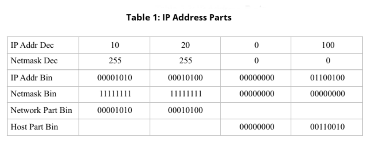
IP Subnetting
IP networks can be broken into smaller pieces by using a subnet. The example in Table 1 is breaking a network with a netmask of 255.255.0.0 into a smaller subnet with a netmask of 255.255.255.0.
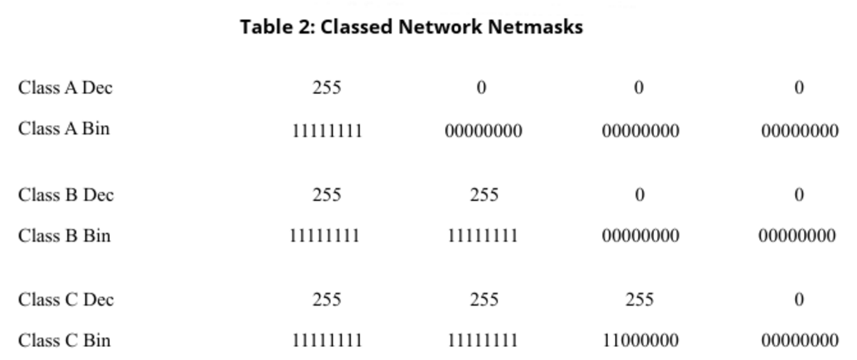
IP Network Classes
Originally, the IPv4 addresses were broken into classes:
-
Class A – 0.0.0.0/255.0.0.0
-
Class B – 128.0.0.0/255.255.0.0
-
Class C – 192.0.0.0/255.255.255.0
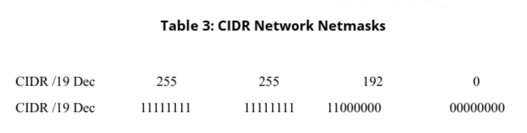
These original classes of networks and subnets did not scale well. Networks which did not fit in a class B were often given a class A. Wasted IP addresses led to the creation of CIDR (Classless Inter-Domain Routing). CIDR uses a numbered bitmask instead of the class bitmask.
Classless Inter-Domain Routing
There are two types of netmasks:
-
Classed Network Netmasks (Table 2).
-
CIDR Network Netmasks (Table 3) are more flexible, and they do not have to end on “nibble” boundaries.
IP Routing
IP packets can only reach from end to end if they are routed properly. Network routers inspect packet headers, and make routing decisions based on the destination address (Figure 2).
IP Management Tools
IP management tools include ifconfig and ip. ifconfig is part of the net-tools package. This historical tool is not very flexible. ip is part of the iproute package. It is the new default tool for many distributions and manages Layer 2 and 3 settings.
Setting an address with ifconfig:
# ifconfig eth0 10.20.0.100 netmask 255.255.0.0
Setting an address with ip:
# ip addr add 10.20.0.100/16 dev eth0
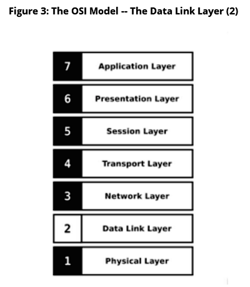
OSI Layer 2: Data Link Layer
The Data Link Layer (Figure 3) deals with transferring data between network nodes:
-
Adjacent nodes in a Wide Area Network (WAN).
-
Nodes on the same Local Area Network (LAN) segment.
Some of the common Data Link Layer protocols are:
-
Ethernet.
-
ARP: Address Resolution Protocol.
-
PPP: Point to Point Protocol.
- STP: Spanning Tree Protocol.
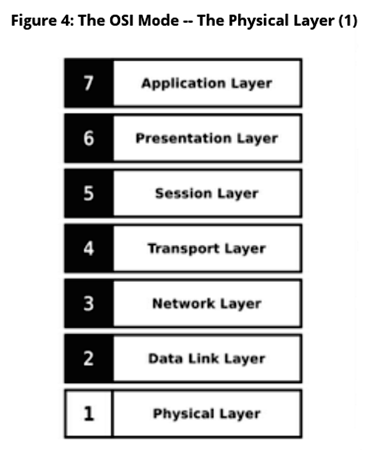
OSI Layer 1: Physical Layer
The Physical Layer is the lowest possible layer and deals with the actual physical transfer of information. This layer deals with transferring bits over a physical medium:
-
Electric pulses over copper cables.
-
Laser pulses over fiber optic cables.
-
Frequency modulations over radio waves.
-
Scraps of paper over carrier pigeons (to learn more, go to http://tools.ietf.org/html/rfc1149).
There are various different protocols, hardware types, and standards defined for different types of physical networks (commonly referred to as PHYs):
-
IEEE 802.3: Copper or fiber connections.
-
IEEE 802.11: Wireless (Wi-Fi) connections.
-
Bluetooth: Wireless connections.
-
USB: Copper connections.
-
RS232: Copper serial connections.
Come back next week for “LFCE Prep Course — LANs, WANs, VLAns and Bridging”. We’ll learn about local area networks, wide area networks, virtual LANs, and bridging.
The Linux Foundation offers both certification tests and training, which you can read all about at Linux Foundation Training. You can become a Linux Foundation Certified Sysadmin or a Linux Foundation Certified Engineer. In this series you’ll get a look at our new Linux Foundation Certified Engineer prep course. The full LFCE course has 12 chapters. Over the next few weeks, we will preview “Session 2: Linux Networking Concepts and Review”.
Read Part 3: LFCE Prep Course — LANs, WANs, VLANs and Bridges (Part 3)
Download the full sample chapter: Linux Networking Concepts and Review.