
Data is only good if it is reliable, accurate and timely. When data is poorly handled, it can produce a number of issues that could stress an IT exec.
Read more at eWeek
 LibreOffice might be a great office suite, but the community doesn’t like the fact that the UI still looks kind of dated. The good news is that anyone with some coding skills can try to fix that by working on the project.
The LibreOffice users have noticed some improvements for the interface that have landed in the past few years, but the office suite has the same general design. This design was OK a decade ago, but that’s no longer the case. The rest of the ecosystems have… (read more)
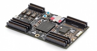 Snickerdoodle is a new maker board designed for people who like building stuff ranging from robots to advanced networking, and it can fit in the palm for the hand.
It seems that no matter how many maker boards there are in the market, there is still room for one more that does something that the rest couldn’t. This type of minicomputers has been around for a while, but the Raspberry Pi made them famous. It attracted a large crowd of users that wasn’t even interesting in usi… (read more)

Our last tutorial in this series used the Raspberry Pi 2’s 40 pin header to connect a touch screen to the Pi. This time around we’ll take a look at how to directly interact with hardware — in this case an electric gearmotor — from the command line using the 40 pin header. The following design can also be extended to allow a Raspberry Pi to be mounted to a small robot and move it (and itself) around.
The Raspberry Pi is a small ARM single board computer which has great community support and has many Linux distributions available for it. The Raspberry Pi 2 is the latest model of the series and includes among other things a quad core ARM, 1GB of RAM, Ethernet, USB, HDMI, microSD, and a 40 pin header for connecting hardware.
First, we’ll need to connect the Pi to the breadboard. The connecting wires that are used on breadboards are Male to Male Dupont connectors, which won’t work with the Pi. You can get Male to Female connectors, and the latter end will let you directly connect to the pins on the Raspberry Pi 2. Another option is to get a “Wedge” which connects the Raspberry Pi using a ribbon cable with a custom PCB that can be inserted into a breadboard. A significant advantage to using a Wedge is that the pins are labeled on the Wedge PCB — much, much simpler than trying to keep count of which pin you are at in the 20 columns of unlabeled pins on the Pi itself.
Next we’ll install the WiringPi project’s “gpio” command line tool which allows interaction with the 40 pins on the Raspberry Pi header. I was using the Raspbian distribution on my Pi. The below commands should checkout the latest source, compile, and install it for you.
pi@pi ~/src $ git clone git://git.drogon.net/wiringPi
Cloning into 'wiringPi'...
remote: Counting objects: 914, done.
remote: Compressing objects: 100% (748/748), done.
remote: Total 914 (delta 654), reused 217 (delta 142)
Receiving objects: 100% (914/914), 285.58 KiB | 123 KiB/s, done.
Resolving deltas: 100% (654/654), done.
pi@pi ~/src $ cd ./wiringPi
pi@pi ~/src/wiringPi $ ./build
The WiringPi library offers easy access to the GPIO pins on the Raspberry Pi and provides both the command line tool gpio and an API for hardware interaction for your programs. It also includes some support for interacting with chips which are connected to the Raspberry Pi. For example, mapping a GPIO pin multiplexer chip for easy access using calls that are familiar with Arduino programmers such as digitalWrite().
WiringPi has its own pin numbering scheme. As you can see from the table below, much of the time the name of the pin and the name that WiringPi uses will match. I used the SparkFun Wedge, which labels the GPIO pins using the BCM numbers. So the physical pin 12 on the Raspberry Pi header has a BCM pin name of 18, and so is labeled as G18 on the Wedge. The same pin has a WiringPi pin number of 1. It seems like there might be one too many levels of indirection in there. But, if you are using a Wedge then you should be able to read the BCM pin number and know what WiringPi (wPi) pin number you need to use in order to interact with that pin on the Wedge. The Wedge also makes it a little less likely to accidentally connect ground and voltage to the wrong places.
root@pi:~# gpio readall
+—–+—–+———+——+—+—Pi 2—+—+——+———+—–+—–+
| BCM | wPi | Name | Mode | V | Physical | V | Mode | Name | wPi | BCM |
+—–+—–+———+——+—+—-++—-+—+——+———+—–+—–+
| | | 3.3v | | | 1 || 2 | | | 5v | | |
| 2 | 8 | SDA.1 | IN | 1 | 3 || 4 | | | 5V | | |
| 3 | 9 | SCL.1 | IN | 1 | 5 || 6 | | | 0v | | |
| 4 | 7 | GPIO. 7 | IN | 1 | 7 || 8 | 1 | ALT0 | TxD | 15 | 14 |
| | | 0v | | | 9 || 10 | 1 | ALT0 | RxD | 16 | 15 |
| 17 | 0 | GPIO. 0 | IN | 0 | 11 || 12 | 1 | ALT5 | GPIO. 1 | 1 | 18 |
| 27 | 2 | GPIO. 2 | IN | 0 | 13 || 14 | | | 0v | | |
| 22 | 3 | GPIO. 3 | IN | 0 | 15 || 16 | 0 | IN | GPIO. 4 | 4 | 23 |
| | | 3.3v | | | 17 || 18 | 0 | IN | GPIO. 5 | 5 | 24 |
| 10 | 12 | MOSI | ALT0 | 0 | 19 || 20 | | | 0v | | |
| 9 | 13 | MISO | ALT0 | 0 | 21 || 22 | 0 | IN | GPIO. 6 | 6 | 25 |
| 11 | 14 | SCLK | ALT0 | 0 | 23 || 24 | 1 | ALT0 | CE0 | 10 | 8 |
| | | 0v | | | 25 || 26 | 1 | ALT0 | CE1 | 11 | 7 |
| 0 | 30 | SDA.0 | IN | 1 | 27 || 28 | 1 | IN | SCL.0 | 31 | 1 |
| 5 | 21 | GPIO.21 | IN | 1 | 29 || 30 | | | 0v | | |
| 6 | 22 | GPIO.22 | IN | 1 | 31 || 32 | 0 | IN | GPIO.26 | 26 | 12 |
| 13 | 23 | GPIO.23 | IN | 0 | 33 || 34 | | | 0v | | |
| 19 | 24 | GPIO.24 | IN | 0 | 35 || 36 | 0 | IN | GPIO.27 | 27 | 16 |
| 26 | 25 | GPIO.25 | IN | 0 | 37 || 38 | 0 | IN | GPIO.28 | 28 | 20 |
| | | 0v | | | 39 || 40 | 0 | IN | GPIO.29 | 29 | 21 |
+—–+—–+———+——+—+—-++—-+—+——+———+—–+—–+
| BCM | wPi | Name | Mode | V | Physical | V | Mode | Name | wPi | BCM |
+—–+—–+———+——+—+—Pi 2—+—+——+———+—–+—–+
Connecting an LED and resistor in series to a GPIO is a standard test to quickly see if setting a GPIO has an effect. Connecting one end of the LED-resistor combination to G18 (BCM18) on the Wedge and the other end to ground allows the below commands to turn the LED on and off.
root@pi:~# gpio mode 1 output
root@pi:~# gpio write 1 1
root@pi:~# gpio write 1 0
Pin G18/BCM18 is special on the Raspberry Pi because it can send a Pulse Width Modulated (PWM) signal. One way of thinking about a PWM signal is that it is on for a certain percentage of the time and off for the rest. For example, a value of 0 means the signal is always a low (ground) output. A value of 1023 would keep the pin high all of the time. A value of 512 would result in the pin being on half the time and off half the time.
The script shown below will give a glowing pulse effect on the LED instead of just turning it on and off directly. Notice the use of the trap command which runs a cleanup function when the script is exited or closed using control-c from the command line.
root@pi:~# cat ./gpio-pwm.sh
#!/bin/bash

pin=1;
minval=10
maxval=1023

trap "{ echo 'bye...'; gpio mode 1 output; gpio write 1 0; exit 0; }" EXIT SIGINT SIGTERM
gpio mode 1 pwm

for i in $(seq 1 10); do

   for v in $(seq $minval 10 $maxval); do
      gpio pwm $pin $v
      sleep 0.001
   done
   for v in $(seq $maxval -10 $minval); do
      gpio pwm $pin $v
      sleep 0.001
   done
   sleep 0.5
done

exit 0
The photo above shows a common method to control an electric gearmotor from a microcontroller or computer. A few complications are introduced when running gearmotors from computers. For a start, the motor is likely to want to run at a higher voltage than what the computer is using. Even if the motor can operate at the voltage that the GPIO pins on the computer operate at, the motor will likely want to draw more current than the computer is rated to supply. So operating a gearmotor directly from the GPIO pins is usually a very bad idea. Damage to the controlling computer has a fairly good chance of occurring if you try that. A common solution to this problem is to use a motor driver chip which drives the motors using a separate power supply and lets you command the chip from your computer.
The small red PCB on the left side of the photo has a TB6612FNG motor driver chip on it. The TB6612FNG is not a DIP chip, so it cannot insert directly into the breadboard. There are many PCBs available like that shown in the photo which contain the TB6612FNG chip and have a pinout that allows for insertion into a breadboard. The chip lets you run two motors at different speeds and directions using a dedicated power source for the motor and control the chip using a different voltage level from a computer. Each motor wants to use three pins on the Raspberry Pi for control; a PWM pin to set the motor rotation speed, and two pins to set the direction that the motor spins.
Shown on the lower side of the TB6612FNG chip, the motor is wired to B01 and B02. It doesn’t matter which way around you wire this, as inserting the motor the other way around will only cause it to spin in the other direction. I’m using a block of AA batteries to power the gearmotor; the battery has its positive lead connected to the VM (Voltage Motor) input and the ground is connected to the ground shared with the Raspberry Pi. Using red and green/black for power and ground is a reasonably common wire color scheme and helps to avoid accidentally connecting things that might create a short circuit. The ground of the Raspberry Pi and the battery pack are connected to establish a common ground. The battery pack supplies the Voltage Motor pin which is used to power the gearmotor. All signals sent to the TB6612FNG chip use the logic voltage level which is set by the Raspberry Pi.
The STBY (Standby) line is pulled to logic voltage high. There is an internal pull down resistor on the STBY pin, and if the STBY is low (ground) then the motors will not turn. The PWMB, BIN2, and BIN1 are connected to G18, G19, and G20 respectively. The G18 pin has a special double meaning because it can output a PWM signal using hardware on the Raspberry Pi.
The first commands shown below will set the motor rotation direction and setup the controlling PWM pin ready to start rotating the motor. The PWM setting defaults to a range 0-1023 with higher values causing the motor to spin faster. Once the motor is stopped, the settings on pins 24 and 28 are swapped, so the motor will spin in the opposite direction.
root@pi:~# gpio mode 24 out
root@pi:~# gpio mode 28 out
root@pi:~# gpio write 24 1
root@pi:~# gpio write 28 0
root@pi:~# gpio mode 1 pwm

root@pi:~# gpio pwm 1 200
root@pi:~# gpio pwm 1 800
root@pi:~# gpio pwm 1 0
root@pi:~# gpio write 24 0
root@pi:~# gpio write 28 1
root@pi:~# gpio pwm 1 800
root@pi:~# gpio pwm 1 0
The same PWM chip that controls wPi pin 1 also controls wPi pin 26. Moving the PWM pin of the gearmotor to wPi pin 26 I could still control the speed of the motor by setting the PWM signal on wPi pin 1. So these pins seem to share the same PWM signal, at least when I controlled them through the gpio tool. Moving the direction setting pins to free up wiring pin 24 (BCM pin 19) allows the use of a second PWM output signal. For example, moving to using BCM_20 and BCM_21 to set the motor direction.
The Raspberry Pi 2 has two PWM outputs. It has been mentioned that using one of those PWMs might affect audio on the Raspberry Pi. A common method of controlling a robot is differential drive which uses two independently controlled motors and a drag wheel or ball as a third point of contact with the ground. Using two PWM outputs and four other GPIO pins the above design can be extended to allow a Raspberry Pi to be mounted to a small robot and move it around.
The Wiring Pi project can also control 595 shift registers, and GPIO extension chips like the MCP23008 and MCP23017. I hope to show interaction with some of these chips using Wiring Pi as well as TWI or SPI interaction in a future article.