On the episode of The New Stack Makers podcast, Dell EMC CTO Idit Levine, an EMC chief technology officer at the cloud management division and office of the CTO, discussed how unikernels are poised to offer all of the developer flexibility afforded to containers, while striving for better security and integrations with many of todays top container platforms.
At KubeCon earlier this month, Levine and the rest of the team behind the open source unikernel compilation and management platform, Unik announced new features for Unik designed to bolster both unikernel adoption and community involvement with the project moving forward. These changes included Kubernetes integration, with users having the ability to run Unik side-by-side with Kubernetes, and adding support for the Google Cloud Platform after continued requests to do so from the community.
I think that the first thing to understand about Git is that it’s not strictly a source control system; it’s more like a versioned filesystem that happens to be good at source control. Traditionally, source control systems focused on the evolution of files. For example, RCS (and its successor CVS) maintain a separate file in the repository for each source file. These repository files hold the entire history of the file as a sequence of diffs that allow the tool to reconstruct any version. Subversion applies the idea of diffs to the entire repository, allowing it to track files as they move between directories.
Git takes a different approach. Rather than constructing the state of the repository via diffs, it maintains snapshots of the repository and constructs diffs from those (if you don’t believe this, read on).
In a perfect world, we would all get along with our coworkers and bosses all the time. Unfortunately, we don’t live in a perfect world.
While most of us make our best efforts to avoid conflict at work, occasionally it is unavoidable. Here are some of my best tips on how to make all of your conflicts in the workplace healthy and (hopefully) productive, so you can move on and get back to what really matters.
1. Give up on the idea of “winning”
The best way to win an argument is to let go of the idea that you actually have something to “win.”
Winning, in this case, doesn’t mean getting your way or showing the opposition how they are wrong. Instead, it means being the person who helps everyone get on the same page so everyone can move forward.
Taking a closer look as to why GTK+ experienced significant speed issues when used with Wayland and HiDPI screens.
—
Written by Gustavo Noronha, Web Domain Lead at Collabora.
Like I wrote before, we at Collabora have been working on improving WebKitGTK+ performance for customer projects, such as Apertis. We took the opportunity brought by recent improvements to WebKitGTK+ and GTK+ itself to make the final leg of drawing contents to screen as efficient as possible. And then we went on investigating why so much CPU was still being used in some of our test cases.
The first weird thing we noticed is performance was actually degraded on Wayland compared to running under X11. After some investigation we found a lot of time was being spent inside GTK+, painting the window’s background.
Here’s the thing: the problem only showed under Wayland because in that case GTK+ is responsible for painting the window decorations, whereas in the X11 case the window manager does it. That means all of that expensive blurring and rendering of shadows fell on GTK+’s lap.
During the web engines hackfest, a couple of months ago, I delved deeper into the problem and noticed, with Carlos Garcia’s help, that it was even worse when HiDPI displays were thrown into the mix. The scaling made things unbearably slower.
You might also be wondering why would painting of window decorations be such a problem, anyway? They should only be repainted when a window changes size or state anyway, which should be pretty rare, right? Right, that is one of the reasons why we had to make it fast, though: the resizing experience was pretty terrible. But we’ll get back to that later.
So I dug into that, made a few tries at understanding the issue and came up with a patch showing how applying the blur was being way too expensive. After a bit of discussion with our own Pekka Paalanen and Benjamin Otte we found the root cause: a fast path was not being hit by pixman due to the difference in scale factors on the shadow mask and the target surface. We made the shadow mask scale the same as the surface’s and voilà, sane performance.
I keep talking about this being a performance problem, but how bad was it? In the following video you can see how huge the impact in performance of this problem was on my very recent laptop with a HiDPI display. The video starts with an Epiphany window running with a patched GTK+ showing a nice demo the WebKit folks cooked for CSS animations and 3D transforms.
After a few seconds I quickly alt-tab to the version running with unpatched GTK+ – I made the window the exact size and position of the other one, so that it is under the same conditions and the difference can be seen more easily. It is massive. Video: https://www.youtube.com/watch?v=XQVqSms5guU
Yes, all of that slow down was caused by repainting window shadows! OK, so that solved the problem for HiDPI displays, made resizing saner, great! But why is GTK+ repainting the window even if only the contents are changing, anyway? Well, that turned out to be an off-by-one bug in the code that checks whether the invalidated area includes part of the window decorations.
If the area being changed spanned the whole window width, say, it would always cause the shadows to be repainted. By fixing that, we now avoid all of the shadow drawing code when we are running full-window animations such as the CSS poster circle or gtk3-demo’s pixbufs demo.
As you can see in this video, the gtk3-demo running with the patched GTK+ (the one on the right) is using a lot less CPU and has smoother animation than the one running with the unpatched GTK+ (left).
Pretty much all of the overhead caused by window decorations is gone in the patched version. It is still using quite a bit of CPU to animate those pixbufs, though, so some work still remains. Also, the overhead added to integrate cairo and GL rendering in GTK+ is pretty significant in the WebKitGTK+ CSS animation case. Hopefully that’ll get much better from GTK+ 4 onwards.
Laptops preloaded with Linux aren’t as rare as they used to be. In fact, big name hardware companies like Dell have whole lines of laptops that ship with Ubuntu installed, and if you want to stretch things a bit you could argue that a Chromebook is a kind of Linux machine (though it takes a bit of tinkering to get actual Linux installed). Still, there’s no question the Linux user of today has a wealth of options compared with the dark ages of just a few years ago when “I use Linux” was code for “I spend all my time looking for hardware drivers.”
Today, what remains unusual even in the midst of this growing interest in PCs shipping with Linux is a company that sells nothing else. There are a handful of organization that do just this, however, and they have done so for some time. These entities range from longtime Linux supporters like System76 to newer efforts from the likes of Purism, which began life with an impressive crowdfunding campaign that raised more than a $1 million to create a line of sleek, Apple-inspired but completely free-software laptops.
This guide will walk you through the various steps you can follow to upgrade your system to Fedora 25 from Fedora 24 using both graphical user interface (GUI) and command line methods.
Although the primary method of upgrading has been provided via the command-line, however, if you are using Fedora 24 workstation, you can take advantage of the GUI mechanism.
Read complete article at Tecmint
Explore Software Defined Networking Fundamentals today by downloading the free sample.Download Now
Join us in this three-part weekly blog series to get a sneak peek at The Linux Foundation’s Software Defined Networking Fundamentals(LFS265) self-paced, online course.
In part one, we introduced the historical background that led to the current virtualization innovation wave. We then introduced the concept of data planes, control planes and management planes and highlighted the role of each. In part two we will learn how traditional data switches are architected and how these planes are implemented. You will learn a fundamental aspect of SDN, namely the separation of the data plane and the control plane.
Traditional Switches
The core of a traditional network switch is based on custom silicon, either an ASIC, FPGA or NPU. Even though FPGAs and NPU’s can be modified in the field, they are still limited in functionality and relatively expensive. These hardware devices can forward packets based on Layer 2 and Layer 3 input at the requisite “wire speed.” The trade off worth noting is performance over flexibility. The control plane handles the routing functions and calculates the packet forwarding rules.
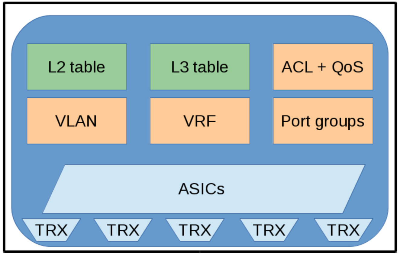
The figure below illustrates a traditional non-SDN switch, with the following components:
•The transceivers (TRX), which are the ports transmitting or receiving communications on the medium (copper, optical, radio frequency, etc.).
• An Application Specific Integrated Circuit (ASIC) is used to handle the incoming and outgoing data packets. An ASIC is a specialized purpose built silicon device that executes just a limited set of tasks, and, in this particular instance, do it very fast (up to 40Gbit/sec per port).
• The Layer 2 and Layer 3 tables are the central building blocks the ASIC acts on.
To fulfill the demands of virtualized servers, Virtual Local Area Networks (VLANs) or Virtual Routing Functions (VRFs), new features have been added for better isolation of the hosts or virtualized machines: Access Control, Quality of Service (QoS), port groups, etc. Most of these features must be configured manually and in different ways for various vendors.
Figure 1: A traditional non-SDN switch.
Traditional Switches and the Three Planes
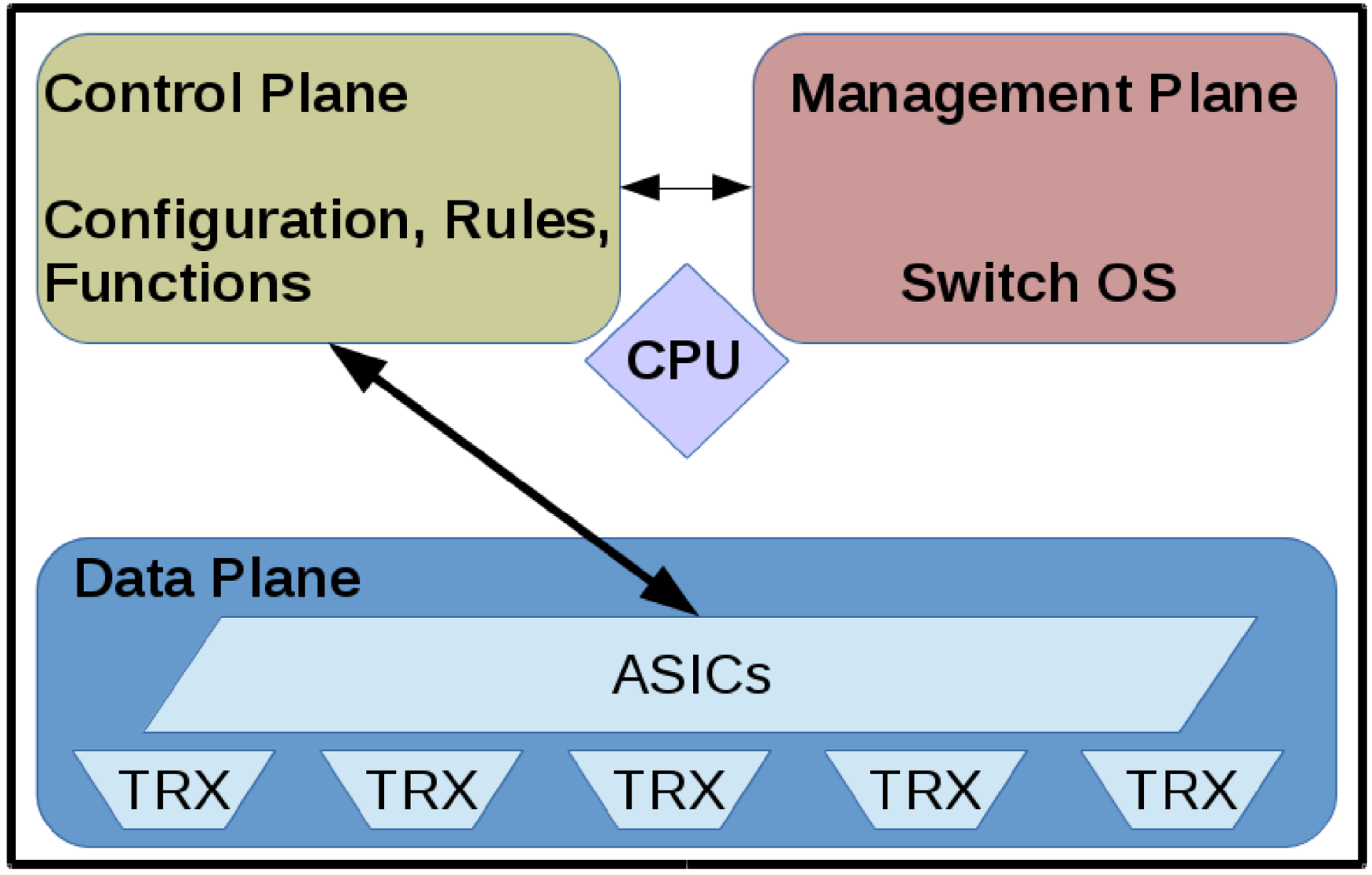
The next figure illustrates what a switch looks like when combining the components of a non-SDN switch with the data, control, and management planes:
• The transceivers (TRX) and the ASIC form the data plane.
• A general purpose CPU hosts both the control and management planes.
• The control plane handles the routing functions and is also responsible for calculating the forwarding rules.
• The management plane is used to set up and change the network switch configuration.
Figure 2: Data, Control, and Management Planes in a Switch.
New Packet Arriving at a Switch
When a packet enters a switch the data plane looks for a forwarding rule based on information in the packet header. If there’s a match the packet is sent on its way. If there isn’t a match, the packet is sent to the control plane where routing (Layer 3) processing occurs and the packet is sent back to the data plane for forwarding to the appropriate output port. The control plane then adds the new forwarding rule to the Layer 2 forwarding table so subsequent similar packets are no longer exceptions and are forwarded at wire speed.
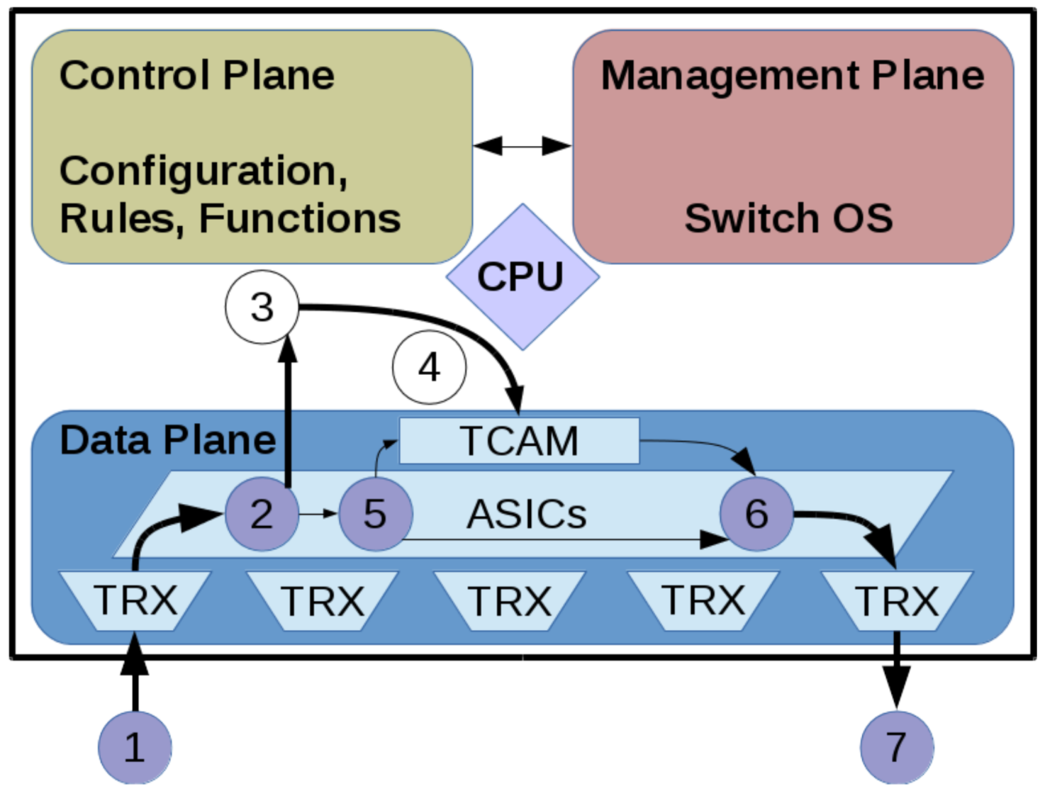
Here’s what happens when a new packet arrives:
1. A new packet arrives on the receiving port and is stored in a buffer.
2. If there is no rule matching this packet in the data plane, the control plane must decide what to do.
3. The control plane receives the packet from the data plane and executes the routing functions.
4. Then, the control plane stores the calculated action (e.g. output port) into the forwarding tables. Forwarding tables are stored in content-addressable memory, for fast and effective lookup and matching.
5. At this point, the data plane can apply the rules stored in the TCAM (Ternary Content- Addressable Memory).
6. The data plane forwards the packet to the output port.
7. The output port then transmits the packet over the medium.
The request to the control plane takes time, because the action needs to be calculated and because the CPU of the control plane runs at a lower speed.
Figure 3: New Network Packet Arriving at Switch.
Subsequent Packet Arriving at a Switch
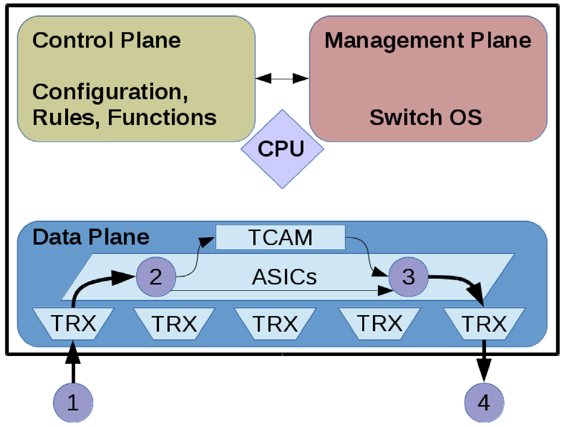
The next packet arriving with the same source and destination will be forwarded based on the existing rules, as long as they are valid and not expired:
1. The packet arrives.
2. It is matched with the rules stored in the TCAM.
3. The packet is then forwarded to the output port.
4. The output port transmits the packet over the medium.
Figure 4: Network Packet with Known Forwarding Rule.
In this article, we reviewed the architecture and operations of a traditional data switch. We showed how the three planes are implemented and how they interact. A fundamental trade-off illustrated is performance over flexibility. This trade off and subsequent limitations lead to the advent of SDN. In part three, we will discuss the implementation and operation of a software defined switch and we’ll introduce the concept of the SDN Controller. Lastly, RFC 7426 will be introduced highlighting the various abstraction layers created to simplify complex data networks.
The “Software Defined Networking Fundamentals” training course from The Linux Foundation is designed to provide system and network administrators and engineers with the skills necessary to maintain an SDN deployment in a virtual networking environment. Download the sample chapter today!
The OwnTracks system allows you to track the location of Android or IOS phones, and it places a huge focus on data ownership. Youget to decide where your location data is sent and what is done with it. In the previous article of the series, we looked at how to install OwnTracks on a phone and set up a personal MQTT server that collects the location data. This time around, we’ll take a look at some of the clients that can be used with the collected location data.
We have already seen a very basic client for our OwnTracks location information by using mosquitto_sub to test that location data is getting through. We will now look at how to set a nice icon for users in the OwnTracks app, take a look at firewall rules to allow MQTT traffic to pass, and then look at the OwnTracks recorder client.
Setting an icon
One of the simplest OwnTracks clients lets you set an icon for each user on your server. Below I am using the image2card.sh script to publish a little headshot for my OwnTracks icon. Just as in the first article, I need to specify the user to publish as, the password, and the certificate of the local CA that I used to set up my mosquitto MQTT server. Notice that my phone is publishing messages on owntracks/ben/g5, and I set the JSON-encoded icon by sending a retained message to owntracks/ben/g5/info. The image I want to use is called ben-headshot.jpg, and I’ll describe the user just as “Ben”.
If you don’t know the exact topic that OwnTracks is using to publish your data, use the below mosquitto subscribe command to print each MQTT message that goes through your server. Grab your phone and tap the little upward-pointing arrow (upload) in the OwnTracks app to generate a new MQTT message and see it arrive on the console:
If you are running a local MQTT server, then you will want to allow Internet traffic to connect to it using TLS, the default port is 8883. Then OwnTracks can connect over TLS to your server and send the location data. So nobody on the Internet gets to snoop on your location data between OwnTracks and your MQTT server.
If the MQTT server is not on your Internet gateway machine, then you will want to do some Destination Network Address Translation (DNAT) on the gateway machine to allow the MQTT server to be reachable from the Internet. The OwnTracks app will be configured to talk to port 8883 on your public IP address and using DNAT the traffic will be forwarded to the MQTT server on your local network. For example, in the following example, the connection is forwarded from the gateway to the MQTT server machine.
To allow OwnTracks to connect from the Internet you might use something like the following — assuming that eth0 is the network interface that connects to the Internet.
This raises a sticky case when your phone gets back home and connects to WiFi. This is a major problem because you really want your smart house to know when you are home.
When your phone connects to your house WiFi, it will get an IP address on the local network of the house. When OwnTracks tries to connect to the MQTT sevrer on your public IP address 2.3.4.5 it might be able to send a packet to that address and have the packet forwarded to your MQTT server. The reply packet is unlikely to get back however.
The reply will have issues because the MQTT server will see that the packet came from an address on the local network and will try to reply directly to the phone. Unfortunately, the phone is expecting the reply to come from 2.3.4.5 and not 192.168.1.30 so will drop the packet.
The iptables commands below aim to solve the case when the phone is connected at home. They perform the same destination network address translation to divert the packet to the MQTT server. The second command performs a source address translation so that the MQTT server will think that the packet came from your Internet gateway machine rather than directly from the phone. This way, the MQTT server will send the reply to the gateway which will then undo the address translation and send the reply back to the phone. The phone then thinks it is sending data to to 2.3.4.5 and getting a reply from 2.3.4.5 and is happy.
You should make sure you are comfortable with what these iptables commands are doing and that they do not allow more traffic to pass than you are comfortable with. DNAT is a fairly common setup that can be found in many articles, doing both SNAT and DNAT as in the above is harder to find examples of.
Recording the data
The OwnTracks Recorder is a client that can record your location history and present a web interface as shown in Figure 1.
Figure 1: OwnTracks Recorder.
There are three ways to get OwnTracks Recorder installed, using the packages provided, using the docker image, or compiling from source. There are package repositories for Debian, CentOS, and Raspbian. If Docker is your thing, then the setup is described here. I’ll install by compiling from source to keep installation as widely applicable as possible.
I am installing from source using Debian 8.1 on an Orange Pi. Some instructions list the kernel headers as being required, but I found that they were not needed to compile. Instead of running ./configure, you simply copy the config.mk.inand make adjustments as desired. I left the default options in place to help keep installation simple. After that, the standard make and install completes the installation.
# apt-get install build-essential libcurl4-openssl-dev libmosquitto-dev liblua5.2-dev libsodium-dev libconfig-dev$ mkdir ~/src$ cd ~/src$ git clone https://github.com/owntracks/recorder.git$ cd ./recorder$ cp -av config.mk.in config.mk$ make$ sudo make install
Configuration is done by editing a file in /etcas shown below. I made the connection to the local MQTT server over TLS so had to specify the path to the certificate file for the MQTT server used in the first article. Again, starting out with the –debug option is useful to make sure recorder program can connect to the MQTT server properly and will receive data as it comes through. Once you are connected, tap the little upward pointing arrow (upload) in the OwnTracks app on your phone to generate a new MQTT message and see it arrive on the console you are running recorder on.
# edit /etc/default/ot-recorderOTR_PASS="FIXME-THIS-IS-NOT-THE-PASSWORD"OTR_HOST="localhost"OTR_PORT=8883OTR_USER="ben"OTR_CAFILE="/etc/mosquitto/conf.d/ca.crt"# ot-recorder --debug 'owntracks/#'...+++++ [owntracks/ben/g5 (plen=111, r=0) [{"_type":"location","tid":"g5","lat":0.1234,"lon":5.6789,"batt":77}]]- 02:36:23 owntracks/ben/g5 tid=g5 loc=0.1234,5.6789 [MOON] 15 Dark Side, The Moon
Notice in the above that a reverse lookup has been performed on the longitude and latitude sent by OwnTracks on the phone. I’ve modified the reported data to show a street number on the moon, but you should see something much closer to the location of your phone printed there.
Although it is nice to be able to see the data from the phone on the console, ot-recorder also presents a web interface, which by default is at http://127.0.0.1:8083/. The web interface has three main sections: a map, a table of locations, and a history or locations.
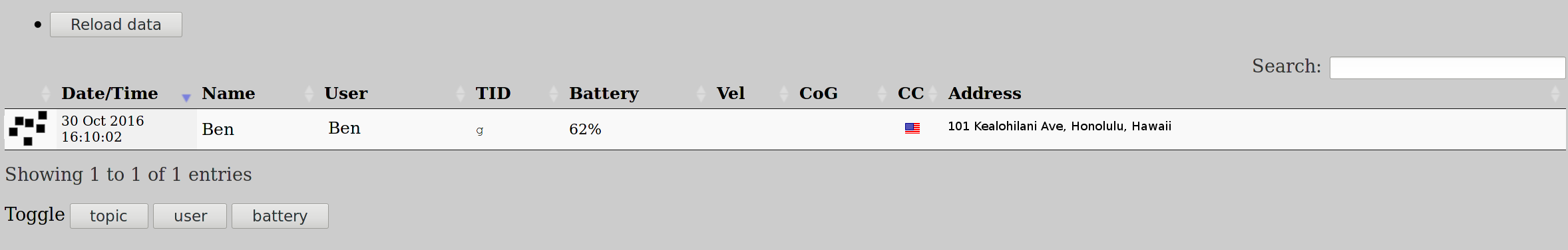
The map shows a Google map with place markers for the current location of all the people who are sending messages to the MQTT server. Each place marker has a click bubble with the address, time, and longitude and latitude reported. The table of locations lets you see the all the people, their location as an address, what time the location was reported, and other data (Figure 2). You can also sort the data by each column. The table of locations is shown below with just me.
Figure 2: Recorder locations.
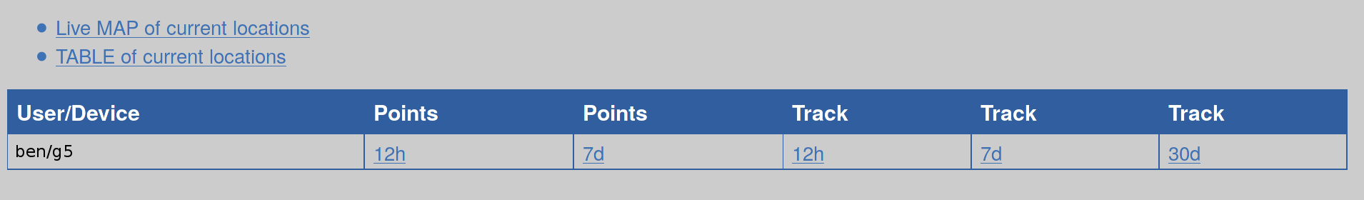
If you have been running ot-recorder to collect data over a period of time, the main table allows you to bring up a map for each user to see on a map what places they have been in the last 12 hours, week, or longer.
Wrap Up
Although there are many documents talking about destination network address translation, you really want to do two translations if your phone is going to connect on the Internet and the local network without requiring any configuration changes.
OwnTracks can integrate location data into both openHAB and Home Assistant. I hope to show this in a later article that first covers setting up one of these home IoT solutions.
The beauty of the Raspberry Pi 3 is that you can tinker and do fun stuff to your heart’s content. This tiny $35 computer lets you do anything.
The Pi I have runs Raspbian for other uses. I keep several micro SD cards, each with different applications and swap them to get more out of the same Pi.
In this tutorial, you’ll learn how to set up a Minecraft machine on the Pi 3 from scratch. Minecraft is a fun game that lets you build whole worlds however you want, by yourself or with friends. Having your own Minecraft server gives you full control over the game.
I set up a Minecraft server because we don’t watch TV, but we have one TV in the kids’ area, and I have hooked a Pi to it so my son can play Minecraft.
In the next two tutorials, you’ll learn how to transform your Pi 3 into your own custom Netflix/Pandora-like streaming service with Plex Media Server and then how to use the Pi as a Plex media player to stream content directly to your HDMI-enabled TV.
What you need:
Raspberry Pi 3
HDMI enabled monitor
Keyboard+mouse
HDMI cable
Power adapter for Pi
Micro SD card (I am using 32GB capacity)
Ethernet or Wireless connectivity
We are using the NOOBS distribution installer, just to make things easier for new users. Download NOOBS from the official site and extract the content. Next, plug in the micro SD card and format it as FAT32. Then copy all the extracted files to the root of the SD card. Note: Don’t copy the entire folder, copy the content of the folder.
Plug the card into the Raspberry Pi , connect the monitor via HDMI, connect the mouse/keyboard and plug in the power supply. If everything goes well, you will see the NOOBS window, where you can choose the OS that you want to install; I recommend Raspbian. Once installed, it will reboot and you are logged into your brand new Raspbian OS running on Raspberry Pi 3. Now connect the network (I recommend ethernet to get faster download speed) and update the system:
sudo apt-get updatesudo apt-get dist-upgrade
If you want you can also change the user password. The default username is pi and the password is raspberry. Change the password by typing the command, and then the new password at the prompt:
passwd pi
Now install these packages for OpenGL Driver for improved graphics:
Here you will see the option to expand the file system and change the password. We don’t need either of those because NOOBS automatically expands the file system and we have already changed the password. Skip everything and go to the advanced option.
Scroll down to find AB GL Driver, hit enter and then select yes to enable. (note: the mouse won’t work, so use the arrow keys).
Reboot the system. Once rebooted, check if OpenGL is enabled, run ‘glxgears’ in the terminal and you should see gears turning.
Install Minecraft packages
First, we need to create directories for Minecraft:
mkdir -p ~/Minecraft/Natives
Change directory to Minecraft:
cd ~/Minecraft/
Now log into your Minecraft account and download the Minecraft.jar file for Linux to the Minecraft directory that we created. Install the launcher and log into your account:
java -jar Minecraft.jar
Click on the edit profileoption and select version 1.8.9 from the list, save the profiles. If you get any error (there is a possibility of an error related to ‘execstack’), please close Minecraft and run these commands to patch some files:
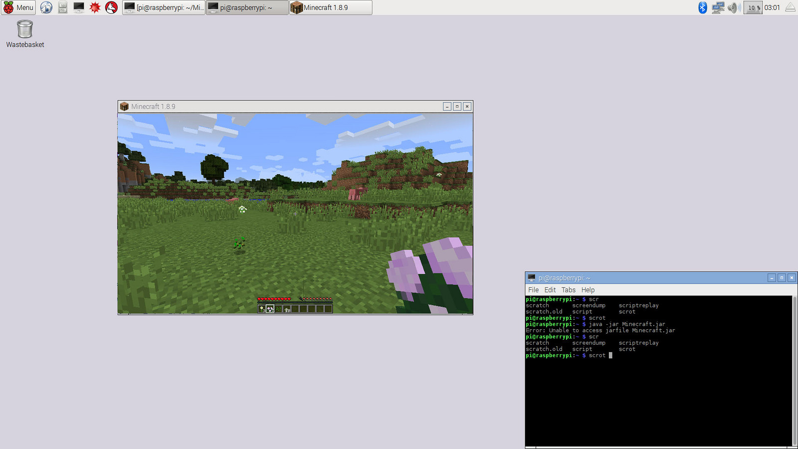
Now either browse to this script from the file manager and open it by clicking on it, or run it from the terminal, and you will have Minecraft running on your machine (image below)
cd ~/Minecraft/./run.sh
That’s it! Once it’s installed, you can start playing Minecraft on your your system. Build new worlds, invite your friends to play on your server, and keep tinkering with your new Pi 3.
For 5 more fun projects for the Raspberry Pi 3, including a holiday light display and Minecraft Server, download the free E-book today!
Today, November 22, 2016, Fedora Project officially announced the release of the Fedora 25 Linux-based operating system, which is a major milestone featuring the latest GNU/Linux technologies and Open Source software.
Six months in development and delayed twice, Fedora 25 Linux is now available for download in its production-ready state, and it appears to be the first ever release of the distribution to ship with the next-generation Wayland display server by default, but only for the Workstation edition, which is built around the GNOME 3.22 desktop environment.
“Wayland now replaces the old X11 display server by default. Its goal is to provide a smoother, richer experience when navigating Fedora Workstation,” said Paul W. Frields, ex-Fedora Project Leader. “You can still choose the old X11 server if required. …